The Rules Tab
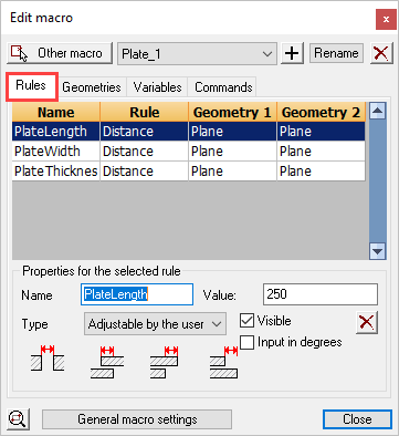
This tab contains a list with an overview of all geometrical rules in the chosen module.
One line in the list presents one rule. The list contains 4 columns. The first is the dimension name - the second column is the type of rule, while the third and fourth columns describe the geometries connected to the rule.
In selecting a rule:
- Options of that rule are shown such as dimension name, value,…
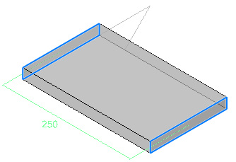
- In the drawing itself the geometries of the rule will be highlighted. In the above example we see that two planes of the plate in a rule defines the width of the plate.
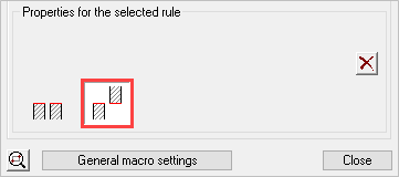
The Properties of rules
The first four properties are only available for dimensions.
Dimension name: This is actually a variable name that is linked to the dimension. We use the variable name as a unique recognition of the dimension in the module. The name must contain at least one character. The name can contain numbers as long as the first character is not a number. A name can only be used once by one dimension within the module.
Visible: This makes the variable visible in the Review macro dialog box. You can hide dimensions that contain formulas and thus cannot be modified. It can also be useful that one can see the value of a dimension without it being adaptable. You can create a dimension with the only purpose of it to view the value of that dimension: for value of the dimension you enter a number (no formula) and you set the type as flexible.
X: With this button you can remove the selected rule.
Value: This can be an ordinary number, a dimension name or an equation. For example “Length1+Length2”.
For more information about the mathematical symbols and equations that can be used, see the Variables tab.
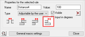
Type: The type determines the flexibility of the value of the dimension:
- Adjustable by the user: The value of the dimension is a number and can be modified during the use of the macro (the dimension will be adjustable in the Review macro dialog box!)
- Fixed value: the value must be a number. This value is not adjustable afterwards during the use of the macro.
- Flexible value: You must use this if other dimensions can influence the value of the dimension. Or it can be used to just 'measure' a distance. If you enter for example an equation then this option must be used (this is generally already done automatically for you).
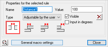
Directions of rules
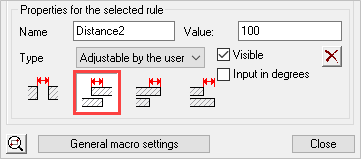
The directions refer to the relationships between objects - of which there are 4 options:
- Gap between Planes
- Planes passing through each other
- Planes are aligned - Plane 1 extends beyond Plane 2
- Planes are aligned - Plane 2 extends beyond Plane 1
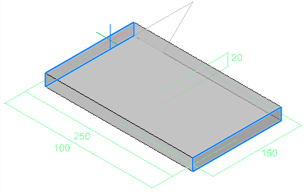
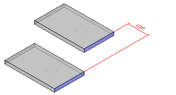
The following examples illustrate the directions:

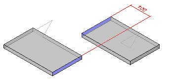
Here the gap between planes of the plates have been set at 100
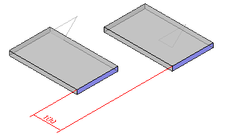
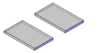
Here the plates overlap one another over a given distance
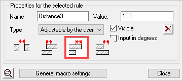
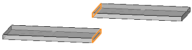
The one plate is put here beyond the other. Which plate is put beyond which plate depends on the order in which the sub geometries were selected during creation of the rule.
Again one plate is put beyond the other but the roles are switched.
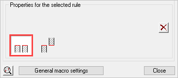
This is the coincident rule. In this case we put the two right planes on each other with the “body” of the plates in the same direction.
The planes in the middle become placed on each other with their body in opposed direction.
There are other situations possible such as distance between plane and line, cylinder and line,… but the functioning is always similar.