Add New Plan Views
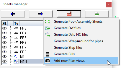
With this tool you can create a new general arrangement view based on a grid, a level, an ISO view or the current 3D view.
The new view will be drawn on a new 2D sheet if no sheet is currently active.
Activating this command will open the Creating Plan views dialog. Here you may select which view(s) to generate by checking one or more items in the list.
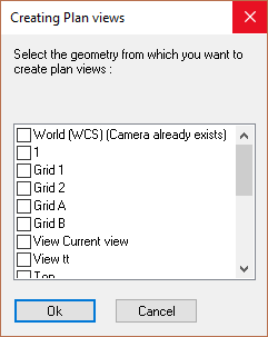
By selecting multiple views you will be prompted to select the position where each view is to be drawn. Unless you've planned exactly where each view is to be positioned within the sheet, this method can lead to some editing of the view placement afterwards.
Placing one view at a time may sometimes be easier. To place one at a time means repeating the Add new plan views process for each view.
After that the Format and scale dialog will appear, enabling you to set the drawing parameters:
The different options in the dialog are explored below :
General tab
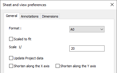
Format - Set the size for the new sheet
Scaled to fit - Selecting this option will set the drawing scale to fit the new view.
Scale - Manually sets the drawing scale. The scale will be set as a ratio to 1.
Update project data - When this is enabled during the Refresh Views operation, then the project data inside the title blocks of the sheet will be refreshed as well. The current Project Data of the 3D project will be entered into the title block.
Shorten along the X or Y axis - When enabled, the view will be shortened in X and/or Y directions. This is usually only used on floor plans for laying out the anchors.
Annotations tab
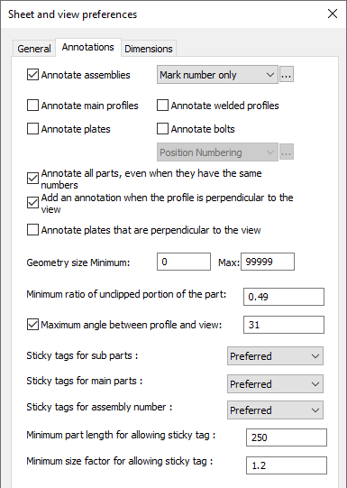
Annotate assemblies - When you activate this, each assembly will automatically receive an annotation. Choose the annotation style for those annotations in the drop-down next to it. More information on the annotation styles can be found at Tools for 2D drawings
Annotate main profiles - When you activate this, each main profile will automatically receive an annotation
Annotate welded profiles - When you activate this, each welded profile (non-mains) will automatically receive an annotation
Annotate plates - When you activate this, each plate will automatically receive an annotation
Annotate bolts - When you activate this, each bolt will automatically receive an annotation
Annotate all parts - When activated, parts that have the same part number will still each be annotated
Geometry size - This options works as a filter for the annotations. Parts smaller than the minimum or larger than the maximum will not receive an annotation. The length of the axis of the parts are used for this filter.
Add ordinate dimensions to the view - Checking this checkbox will add ordinate dimensions to the view.
Add dimension when the profile is perpendicular to the view - Checking this checkbox will add dimensions when the profile is perpendicular to the view - it will not add dimensions when the profile is at an angle to the view.
Back of Angle Leg / Back of Channel is dimension reference - Checking this checkbox will place dimensions from the back (Heel) of the channel or angle.
Top of Steel is reference in side views - Checking this checkbox will make the top-of-steel the reference for placing of dimensions.
Add dimensions for extents of assembly - Checking this checkbox will add O/All dimensions to the view.
Geometry size Minimum - This options works as a filter for the dimensions. Parts smaller than the minimum will not be dimension-ed. The length of the axis of the parts are used for this filter.
Minimum ratio of unclipped portion of the part - Sometimes parts can be drawn partially on a view. This happens when the part is clipped by one of the camera's boundaries. With this setting, you can choose whether clipped parts should be annotated or not.
A ratio of 0.5 means the part needs to be on the view for at least half of it's size. A ratio of 1 would mean that parts that have any clipping should not be annotated at all.
Maximum angle between profile and view - With this setting you can choose whether members that are not drawn flat on the view should be annotated. An angle of 0° means only members drawn flat on the view get annotations.
An angle of 45° could for example be a bracing, or any part in case of isometric views.
Do note that there is another related option in this dialog called Annotate profiles/plates that are perpendicular to the view.
When this option is enabled, and the part is perpendicular to the view, then it will be annotated regardless of this maximum angle setting.
Parts that are exactly perpendicular to the view are often interesting parts to be annotated, and for this reason they can be enabled separately.
Sticky tag options - You can find more about these sticky tag options in the Annotations and dimensions topic.
Dimensions tab
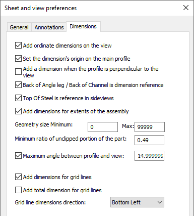
Minimum ratio of unclipped portion of the part - Sometimes parts can be drawn partially on a view. This happens when the part is clipped by one of the camera's boundaries. With this setting, you can choose whether clipped parts should be dimensioned or not.
A ratio of 0.5 means the part needs to be on the view for at least half of it's size. A ratio of 1 would mean that parts that have any clipping should not be dimensioned at all.
Maximum angle between profile and view - With this setting you can choose whether members that are not drawn flat on the view should be dimensioned. An angle of 0° means only members drawn flat on the view get dimensions.
An angle of 45° could for example be a bracing, or any part in case of isometric views.
Do note that there is another related option in this dialog called Add a dimension when the profile is perpendicular to the view.
When this option is enabled, and the part is perpendicular to the view, then it will be dimensioned regardless of this maximum angle setting.
Parts that are exactly perpendicular to the view are often interesting parts to be dimensioned, and for this reason they can be enabled separately.
Add dimensions for grid lines - When you enable this, dimensions between parallel grid lines will be added.
Add total dimension for grid lines - When you enable this, 2 total dimension for parallel grid lines in the X and Y direction will be added.
Grid line dimensions direction - Choose the location of the grid dimensions on the view