Sheets Manager
Command - Prb_Sheets
The Sheets Manager enables you to manage all the output that results from the 3D model.
This includes: Position and assembly sheets, Bills, Schedules, and General arrangement & detail drawings.
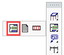
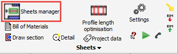
The Sheets manager dialog can be accessed from the main ToolBar - which, when opened, will remain open until it's closed, or may be docked to the edge of the work area.
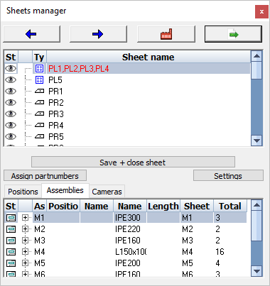
This dialog contains the following main elements:
Top buttons
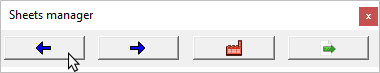
The Top buttons allow you to view, generate, export and print drawings and CNC files.
Activating the left and right arrows enable you to view and scroll through all the 2D drawing sheets that have been prepared
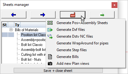
Activating the Generate button allows you to:
- Generate Position and assembly sheets
- Generate DXF files
- Generate DSTV NC files
- Generate WrapAround for pipes
- Generate step files
- Generate bills of materials
- Add plan views and elevations to general arrangement drawings
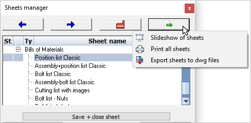
Activating the Export button allows you to:
- Create a slide-show of drawing sheets
You can enter the delay in seconds between sheet display.
The slide show may be terminated at any time by selecting the Stop button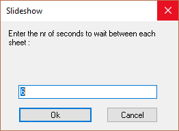
- Print all sheets
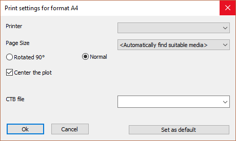
Activating this command will print all 2D sheets listed in the Sheets manager - the following dialog will prompt you to: - Select the printer
- Select page size
- Select the desired CTB plot file
- You may then save these settings as default values for the current format
- Export sheets to DWG files
Activating this command will export all drawing sheets listed in the Sheets manager in DWG format. The file will be located in the same folder as the location of the 3D model.
Top List
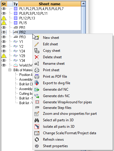
The Top list contains all the 2D sheets created, and also all available bill of materials. Right clicking a 2D sheet in this list will bring up a series of available tools.
Bill of Materials
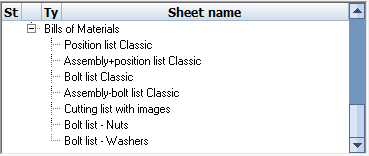
Scrolling to the bottom of the top list, there are a number of pre-defined materials lists.
Double-clicking a bill here will generate just that bill and will also open it in the default editing program as it was set in Windows.
Right clicking on any of these BOM items will bring up the available BOM tools.
Bottom List
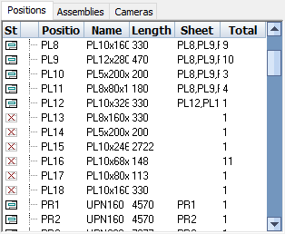
The Bottom list reflects all 3D parts in the drawing. Each member or plate is listed here according to it's position or assembly number. Right clicking on an assembly in this list will bring up a series of options.
At the head of the bottom list, there are a number of options:
Save and close sheet - will save and close the current sheet
Assign part numbers - this tool will assign part numbers to all the parts in the drawing. To learn more of how this is done, see the Numbering chapter.
Settings - For adjusting the settings for BOMs, CNC output, workshop drawings and GA drawings (For more about this see Document generation Settings)
The Tabs: Positions / Assembles / Cameras - these tabs provide a way to filter the bottom list on the part type
Left or Right-click on the list's headers
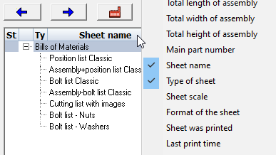
You can Right-Click on the headers of both lists to add or remove columns from the list.
You can also Left-Click on the headers to sort all of the items in the list based on the header that you clicked. The last-clicked header gets first priority in the sorting, the header that was clicked before the last-clicked header gets second priority, etc...