Editing the Profile Library
Add a Profile to the Profile Library
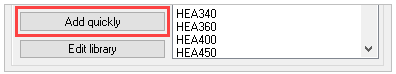
The Add quickly button will add a new profile to the active Value Table.
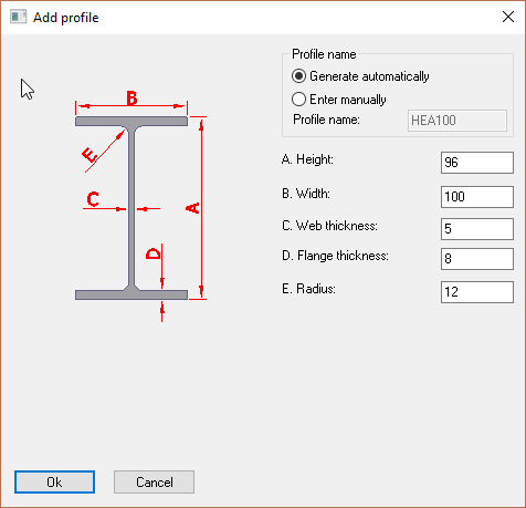
Profile name
The options are to Generate automatically or Enter manually.
Selecting 'Generate automatically' will automatically add the Type to the profile i.e. IPE. In this mode the Profile name window will be grayed out.
Selecting 'Enter manually' will allow the user to change the profile name manually.
By adding the relevant dimensions the new profile will be added to the active Value table.
Edit the Profile Library
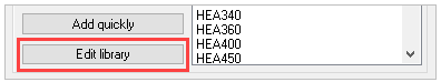
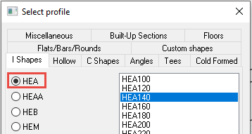
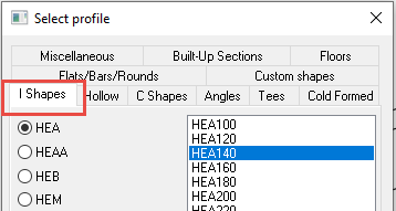
Selecting this tool will bring up the Edit profile library dialog. At the top left of the dialog there are 2 tabs: Overview and Value tables
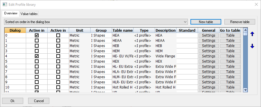
Overview tab
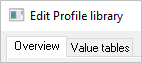
Selecting the Overview tab will show a table, wherein each row represents a profile table.
The purpose of each columns are explained below:
- Dialog priority - which establishes the order of the profile table in the Draw profiles dialog box. The lower the is value, the higher it will be listed in the Select profile dialog box.
- Active in Metric - If you are working on a Metric 3D drawing and this checkbox is activated, then this profile table which will become visible in the Select Profile dialog.
- Active in Imperial - If you are working on a Imperial 3D drawing and this checkbox is activated, then this profile table which will become visible in the Select Profile dialog.
- Units - Indicates whether the contents of the profiles table is in millimeters or in inches
- Group name - Indicates which Group the row belongs to. Each group name represents a tab in the Select profile dialog box
- Table name - The table filename this profile group is linked to. You can find this filename in the folder : \Parabuild\Pb_Lib\Prof\
- Type - Refers to the section type that the profile table is using
- Description - Provides a description of the profile. This description is the name of the table as it is shown in the Select profile dialog box.
- Standard - Describes the international standards for the selected profile table
- General settings - Will bring up the Section Table Options dialog, whereby the user may modify general settings of the profile table.
- Go to Table - will take the user to the Value tables tab dialog, where all the contents and options of the table can be modified. See below.
Value tables tab
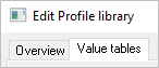
The Value tables will vary according to the profile Type, however, the first 4 columns are consistent for all Types:
- File name - is the file name for the table which has the suffix .pr which is stored in the folder : c:\parabuild\Pb_Lib\Prof\
- Sysname - The system name of the profile that Parabuild needs internally for the unique recognition of the profile. The value must not be one already used by another profile in the table. The prefix (name of the table) is put before this text to obtain the complete system name. This system name is usually not used in the bills of materials or dialog boxes: Parabuild uses this name internally only. This system name is required because Parabuild needs to have a unique name that is independent of the name of the profile in other languages.
- I/O - You can deactivate the individual profile so that it becomes invisible in the Select profile dialog box without having to remove it. Parabuild will nevertheless recognize the profile if it was drawn in a drawing. Therefore if you deactivate the profile here it only has influence on the Select profile dialog box.
- Name - The name of the profile that Parabuild uses everywhere for identification (dialog boxes, bill of materials, shop drawings …)
All columns that follow hereafter are columns that define the dimensions of the profile (height, width, thickness,…). These columns can differ depending on the type of section that was chosen for the table.
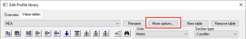
Section table options
With the More options button on the Value tables tab, we can access more advanced options of the current table :
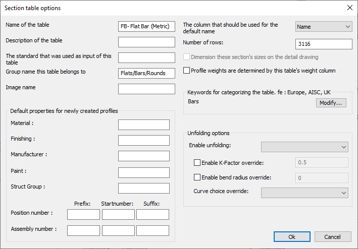
We will explore all of the options in this dialog box :
Name of the table - This is the name of the table as it should appear in the profile selection dialog box :
Description of the table - Use this to give a more full description of the table (this text is currently not shown in any other dialog boxes)
The standard that was used as input for this table - This text is currently not shown in any other dialog boxes)
Group name this table belongs to - This text string will determine in which tab the table will appear in the profile selection dialog box :
Use the English group names that are already in use.
Translation of this text to other languages is done at run-time using Automatic Text Translation.
Enter a new groupname only in case you want to create a new tab in the profile selection dialog box.
Image name - Currently not implemented
The column that should be used for the default name - Select the column here that should be used for the name of the sections inside the Bill of materials and shop drawings. This is especially important when the same section can have a different name in other languages.
Number of rows - Use this setting to quickly add or remove many rows at once
Profile weights are determined by this table's weight column - When enabled, Parabuild will use the weight column in this table to determine the part's weight. When disabled, Parabuild will use the geometric area of the section in combination with the material to calculate the part's weight.
Keywords - Enter keywords here that are related to the table, such as AISC or Europe. The Library Localization tool uses the keywords to allow the user to quickly enable section shapes that have a certain topic or that are for a certain area.
Default properties for newly created profiles - When any of these values are used, the new profiles that are drawn with this table will automatically receive the properties. A practical example for use of this feature is grating : all Grating panels will receive the part number prefix GRTG because it was set in the Grating tables.
Unfolding options
The section tables is usually the best location to activate the unfolding of parts.
The section table settings can be overridden in the Advanced properties of each individual part though.
This is a breakdown of all the unfolding options in the section table :
Enable unfolding - This dropdown has the following choices :
- Disable folding - Use this option if you don't want the unfold operation to be activated on profiles drawn with this section table
- Enable unfolding - Use this option if you want the unfold operation to be activated on profiles drawn with this section table
Enable K-Factor override - Enter a value here if you want to specify a specific K-Factor for this section table
Enable default bend radius override - Enter a value here if you want to specify a bend radius for this section table. This bend radius will only be used on sharp edges.
Curve choice override - When unfolding, the bends are not only neutralized from the part, but also the part is flattened to a 2D plate. As a consequence, there are multiple ways in which the flattening can be done. These are the available options for the flattening :
- Minimum material - Always assume the minimum amount of material
- Maximum material - Always assume the maximum amount of material
The difference between minimum and maximum material is most easily explained with an example : 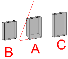
A. is the part being flattened to 2D
B. is the resulting plate after choosing the minimum material option.
C. is the resulting plate after choosing the maximum material option.
- Top surface of the unfolded part - Always assume the top surface of the part
- Bottom surface of the unfolded part - Always assume the bottom surface of the part