Member
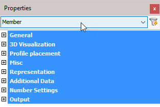
The 'Member' object type has the following headings:
General: Is common to all object types, and covers general AutoCAD and BricsCAD settings, including: Color / Layer / Linetype / Linetype scale / Plot style / Lineweight / Transparency / Hyperlink / Handle /
3D Visualization: Is also common to all object types and includes: Material.
The material that is referred to here is only the visual representation material. For changing the actual material of parts, see the Additional Data section of plates, profiles or structures.
Profile placement
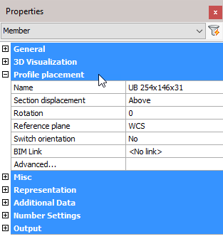
Name: Clicking the button will open the Select Profile dialog where you can select a different profile from any of the groups. Changing the profile will reflect immediately on the drawing.
Section displacement: Select a new section displacement point from the drop-down menu (This value will be Unavailable when the member is not determined by a macro)
Rotation: Enter a new value for the rotation of the profile (This value will be Unavailable when the member is not determined by a macro)
Reference plane: Select a Reference plane from the drop-down menu (This value will be Unavailable when the member is not determined by a macro)
Switch orientation: Enables you to switch the orientation of the profile. For more information, refer to Switch Profile Triangle Direction (This value will be Unavailable when the member is not determined by a macro)
BIM link: Select options from the drop-down menu (This value will be Unavailable when the member is not determined by a macro)
All placement options: This will open the Profile Placement dialog
This value will be Unavailable when the member is not determined by a macro
However, it is possible to automatically create a placement macro for a member when the placement options are set to Unavailable.
Just click on the All placement options button, then the macro will be created automatically.
A model line will be searched for near the profile. If no model line was found, then a new model line will be drawn on the axis of the profile.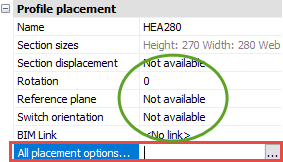
This will give you more flexibility : you can use the placement tools to rotate or displace a profile, even after the original macro was already deleted.
Misc
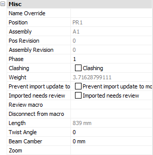
Note! - * indicates that the given value is a resultant of the sum of other values in the panel - and cannot be individually edited.
Name override: The replacement of the normal profile name. This replacement name will be used in all part lists and workshop drawings.
Position: * The number automatically given to elements by Parabuild. Elements that are the same, (same dimensions, holes, sections) are given the same position number. These positions are partially adaptable with prefixes and suffixes, see Number settings.
Assembly: * The Assembly number automatically given to elements by Parabuild
Pos revision: This value is automatically assigned by Parabuild. Whenever the part is created or modified, then it will get the current revision that is currently active in the Revisions manager.
Assembly revision: This value is automatically assigned by Parabuild. Whenever the assembly's parts or the distance between the parts has modified, then it will get the current revision that is currently active in the Revisions manager.
Phase: Change the project phase of the selected element
Clashing: This is set to yes or no and refers to whether the profile is currently clashing with other elements or not. This property is automatically set by the clash control, and is primarily included in properties for search objectives. For more information read the chapter Clash Check
Weight: * Calculated weight of the selected member
Prevent import update to model: Activating the checkbox will prevent any import update to the model. This refers to CIS/2 or Ifc incremental imports.
Imported needs review: This value will be set automatically for parts that were updated after an incremental CIS/2 or Ifc import.
Review macro: Will open the macro edit dialog, where the macro may be viewed and/or edited
Length: * Calculated member length
Twist angle: The angle that the profile has to turn over the length of the profile. This should only be used for profiles on a spiral path or other special 3D-forms.
Beam camber: The camber (distance) to be used for the beam. This value influences the position number of the beam. This value is exported to KISS files.
Zoom: Zoom to the extents of the selected member
Representation
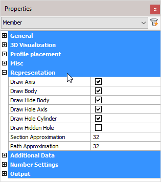
Draw Axis: Draws the Axis of a profile
Draw Body: Draws the complete 3D-model of the profile in 2D wireframe
Draw Hide Body: Draws the complete 3D-model of the profile in 3D visual styles
Draw Hole Axis: Draws the axis of every hole in the profile
Draw Hole Cylinder: Draws the cylindrical path of all holes in the profile in 2D wireframe
Draw Hidden Hole: Draws the cylindrical path of all holes in the profile in 3D visual styles.
One can activate the hole subtraction here for a better visual representation, but do note that when a bolt is drawn through this hole, you would not see the difference. On top of that, the subtraction is heavy on resources. This is the reason why this option is disabled by default.
The edges of the hole are always drawn independently of this setting.
Section Approximation: Determines how accurately the cross section of a profile should be drawn. This has a particular influence over curves in a cross section, for example when the rounding between a beam web and flange is applied.
Path Approximation: Determines how accurately the profile is drawn over its path. This has a particular influence on curved profiles
Additional data
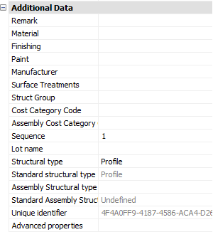
Remark: Can be used in a variety of ways. This field is maintained for every element. It has its own column in the part lists, and can be used for sorting part lists and workshop drawings. This property has no further influence
Material: This field also has its own column in the part lists and can be used for sorting, but this has a direct influence on the position number (and consequently the mark/assembly number). Two elements that are identical, but have another material assigned to, will be given another position number. This enables a total categorization of different materials in part lists and workshop drawings.
The weight factor of every material can be changed in the Parabuild Properties - Global - Material/Finishing. Parabuild will use this weight factor to calculate the weight in the part lists.
Finishing: Same as Remark
Paint: Same as Remark
Manufacturer: Same as Remark
Surface Treatments: This will open the Surface Treatments dialog. It allows you to add new surface treatments or modify existing surface treatments.
Struct Group: This property can be freely used for the user's own purpose.
Cost category Code: These codes are usually determined while a quote for the project is made. This code can then later be assigned to the 3D model when the project was ordered. This way the parts can be traced from estimation to production and to completion inside ERP/MIS software. This value is exported to KISS files.
Assembly Cost category Code: See ‘Cost category Code’
Sequence: The erection sequence of the part. The sequence of a part has the following capabilities:
- The reference assembly of a bolt can be determined by the sequence number of the assemblies
- The sequence is exported to KISS file
- It should be available in bills when you make the columns : %PbColSequence%
- A planning tool for erection is a future addition
Lot Name: The lot that the part belongs to. This value is exported to KISS files
Structural Type: For example: Bracing/Rafter/Stringer/Handrail/Post/etc.... You can use the variable %PbColStructuralType% to use this property in Bill of materials or annotations
Assembly Structural Type: For example: Stair/Railing/etc.... You can use the variable %PbColAssemblyStructuralType% to use this property in Bill of materials or annotations
Unique Identifier: The Unique identifier is allocated by Parabuild, or received from a CIS/2 or Ifc file import.
Advanced properties - Clicking on this button will open the advanced properties dialog, which contains the following properties for profiles :
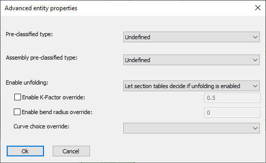
- Pre-classified type and Assembly pre-classified type - This property is only useful for template drawings of connections/macros.
This setting is a good alternative way to automatically assign structural types when it is too difficult or impossible to create filters that detect the type of part automatically.
To make this work, you first have to set the pre-classified structural type here, and then save the template drawing in the library. Then the next time when the template drawing is used and inserted into the drawing, then this pre-classified structural type will be set in the structural type property of the part upon insertion.
The purpose of this is to have an influence on the automatic assignment of the structural part type property, without having to rely on the automatic Structural types assignments through Object Filters.
The unfolding options in the advanced properties of a part take precedence over all other unfolding settings (that may have been set in the section table for example).
- Enable unfolding - This dropdown has the following choices :
- Disable folding - Use this option if you don't want the unfold operation to happen on this part
- Enable unfolding - Use this option if you always want the unfold operation to happen on this part
- Let section tables decide if unfolding is enabled - Use this option if you want the section table settings to decide whether the part should be unfolded. This is the default setting.
- Enable K-Factor override - Enter a value here if you want to specify a different K-Factor for this part
- Enable bend radius override - Enter a value here if you want to specify a specific bend radius for this part. This bend radius will only be used on sharp edges.
- Curve choice override - When unfolding, the bends are not only neutralized from the part, but also the part is flattened to a 2D plate. As a consequence, there are multiple ways in which the flattening can be done. These are the available options for the flattening :
- Minimum material - Always assume the minimum amount of material
- Maximum material - Always assume the maximum amount of material
The difference between minimum and maximum material is most easily explained with an example : 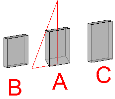
A. is the part being flattened to 2D
B. is the resulting plate after choosing the minimum material option.
C. is the resulting plate after choosing the maximum material option.
- Top surface of the unfolded part - Always assume the top surface of the part
- Bottom surface of the unfolded part - Always assume the bottom surface of the part
Number settings
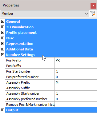
Pos Prefix: Determines the prefix of the position number.
Pos Suffix: Determines the suffix of the position number.
Pos Start number: Determines the start number of the position number.
Pos preferred number: Forces Parabuild to use the preferred number as position number. Parabuild will comply if this number is not already in use by a different part.
Assembly Prefix: Determines the prefix of the Assembly number
Assembly Suffix: Determines the prefix of the Assembly number
Assembly Start number: Determines the start number of the Assembly number
Assembly preferred number: Forces Parabuild to use the preferred number as assembly/mark number. Parabuild will comply if this number is not already in use by a different part.
Remove Pos & Mark number history: Lets Parabuild forget the preferred numbers and also the previous numbers that the part had.
Note! For more information on any of these items, refer to Numbering of elements
Output
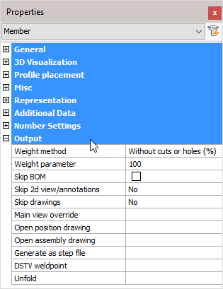
Weight method:
- Without cuts or holes (%): The weight of the complete length of the profile will be calculated, without subtracting the holes and cuts. In the next property you can adjust the percentage of this value that should be used.
- Cut: The cuts in the profiles are subtracted to calculate the weight.
- Cut and drilled: The cuts and the holes are subtracted to calculate the weight
- Fixed value: The value you enter in the next property will be used as the weight for this element in kg or lbs (This value will be taken over in the BOMs without any adjustments).
Weight parameter: This property is being used in combination with the above properties ‘Default’ and ‘Fixed value’
Skip BOM: If this property to ‘Yes’, this element will not appear in the BOMs
Skip 2D view/annotations: Adjust this to skip this element for the 3D annotations or the 3D annotations + 2D view
Skip drawings: You can skip only the Position drawings, only the mark/assembly drawings, or both the Position and Mark drawings
Main view override: Select a plane that determines the main view's direction
Open position drawing: Will open the position drawing of the selected part
Open assembly drawing: Will open the assembly drawing of the selected assembly
Generate as a STEP file: STEP file is a CAD file format, usually used to share 3D models between users with different CAD systems. Note! This command will only work in BricsCAD and when the Communicator module is installed and licensed. For more information, refer to Document generation Settings > Generate STEP Files
DSTV weld point: DSTV weld points are points that are placed in the automatically produced DSTV NC-files. A point indicates on which spot an element must be welded on the profile. For more information, refer to parabuild Settings > Global > DSTV Weld points
Unfold: Will unfold or develop a sheet metal object. Note! This command will only work in BricsCAD and when you have an active sheet metal license.
This tool does the following actions sequentially :
- Convert the profile to a 3D Solid
- Convert the solid to a sheet metal object
- Repair the sheet metal
- Create bends automatically
- Unfold the sheet and write the result as a DXF file in the 3D model's directory and that carries the part number of the strip as name.