Reviewing and modifying welds
The 3D Weld objects drawn by AutoWeld, the context modeler, or by macros can be reviewed and altered after the commands are finished.
You can use The Properties Panel on them or double-click on the welds to review or modify them.
The weld object in 3D does not have a simplistic 1-to-1 relation to the resulting weld symbols on shop drawings. Modeling welds in 3D is focused on flexibility, convenience and efficiency while shop drawing symbols are more about the standards and reducing excess symbols.
The same welds can be constructed in the 3D model in several ways, with different methods affecting how the 3D weld can be modeled and edited even though the different styles may have the same BOM and shop drawing end results.
Here are 3 scenarios of how the welds could be drawn differently for the same baseplate, and what that difference means for you practically while modeling :
- In this example, the 8 weld segments are all drawn as separate segments in a single 3D weld object.
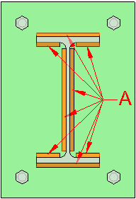
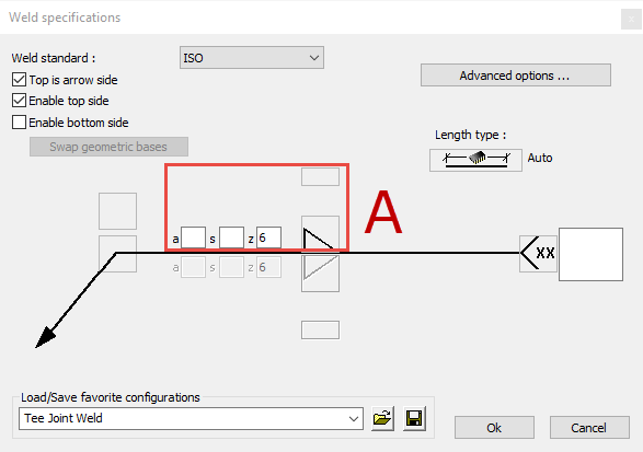
This means that the fillet size only needs to be modified once in the arrow side setting of the weld tag dialog box.
As a downside, it is in this case not possible to quickly change the arrow side segments differently from the other side segments.
In shop drawings these welds may still be automatically grouped into arrow side / other side symbols to reduce clutter. - In this example, the 8 weld segments were drawn with the help of the arrow side / other side tool of the weld tag, in a single weld object.
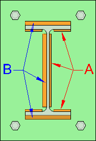
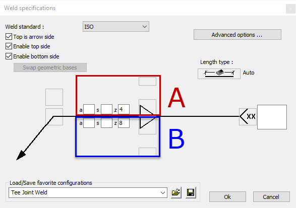
The fillet size can now be modified separately per side. The user will have to make changes to each weld side separately.
In shop drawings the corresponding weld symbols will likely be similarly grouped. - In this example, 2 separate weld objects were drawn : one for the outside of the I shape, and another one for the inside of the I shape.
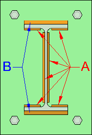
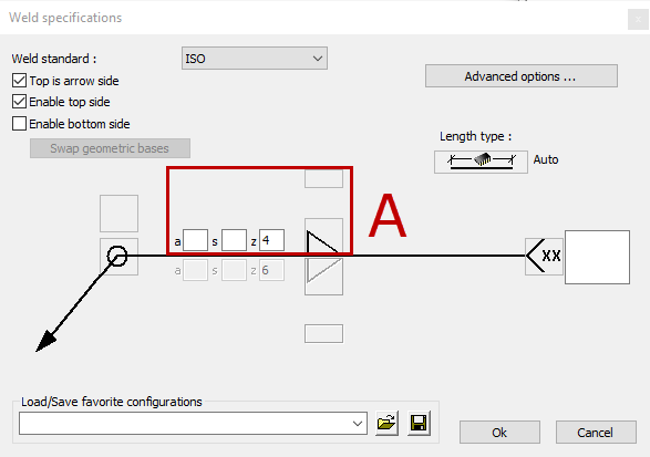
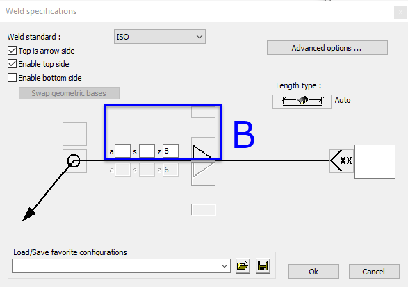
This offers useful flexibility in changing weld sizes per side, but we have drawn 2 separate objects which changes the way we need to modify the welds in the 3D model.
Again, in the shop drawings these welds may still be automatically grouped into arrow side / other side symbols to reduce clutter.