AutoWeld
Command - PrB_AutoWeld
This command will automatically draw 3D welds for the most frequently used structural weld types.
A traditional hurdle with modeling welds is the amount of work involved for the detailer. To make this go a lot faster we created the AutoWeld engine that can automatically create welds based on very flexible rulesets that the user can customize. Different weld types and sizes can be automatically assigned by a ruleset based on all available model information like plate thickness, angle, structural types and much more. The standard Parabuild ruleset will create most structural welds automatically and can be used as the base for your own customized fabricator specific rulesets.
Further editing of the automatically created welds is then easily and quickly done using the properties panel or the weld editing dialog, making the overall process very efficient.
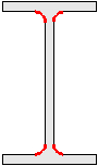
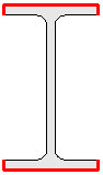
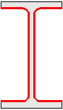
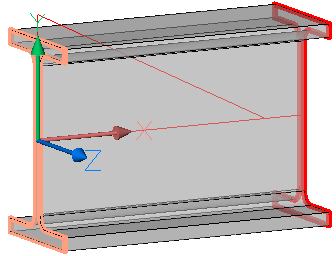
Some examples of welds that can be drawn automatically with varying settings :
Requirements
The following requirements should be met before using this command :
- The 3D parts that you want to add welds to should be touching or nearly touching. Parabuild will use the position of parts relative to each other to determine which welds to add.
- The 3D parts should already be organized into assemblies if you want this command to draw shop welds. This is not a requirement if you want to draw site welds. You can use the Attach command to organize the parts into assemblies by attaching sub parts to their main part. Parts drawn with macros are usually already attached to their main parts.
This command will only draw 3D welds between parts that do not have a 3D weld between them yet. So you can use the command multiple times without having to worry about duplicate welds being drawn.
This means if you want to redo the automatic 3D welds, you will have to delete the existing 3D welds first. A shortcut for deleting existing 3D welds was added at the top of the dialog for convenience.
Disclaimer
Welds created automatically will get sizes that may not sufficiently account for loads and stresses. All welds should be checked versus engineer specifications.
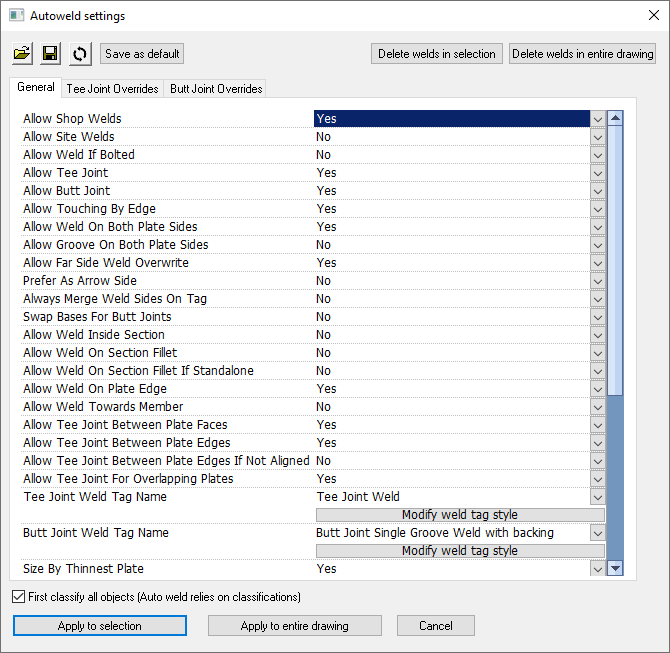
This is a full breakdown of all the different options that are available in the dialog box of AutoWeld :
 Use this button to open a previously stored AutoWeld settings file. The settings file contains all of the setting values and overrides inside this dialog box. This tool can be used to save and re-use the company's welding standards.
 Use this button to save the current settings to an AutoWeld settings file. The settings file contains all of the setting values and overrides inside this dialog box.
 This button allows you to reset all of the settings in the AutoWeld dialog to the Parabuild defaults.
It shows a dialog that allows you to change the most common weld settings : 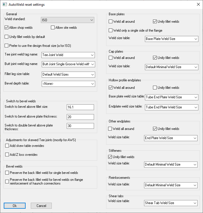
These options are also available in the main AutoWeld dialog, but this dialog is a way to quickly configure the AutoWeld settings with some common settings, without having to resort to editing the more complex AutoWeld settings and overrides.
For more detailed information about these options, see the General tab below.
*Note* The option Switch to bevel will consider sizes above the given fillet size.
The option Switch to double bevel will consider sizes above the given plate thickness.
 When you press this button, then the current settings in the dialog will be saved as default for the next Parabuild sessions. So the next time that you start Parabuild, these settings will be loaded.
 This will delete all 3D welds from a selection. AutoWeld does not draw a new weld between two parts if they already have a weld between them. So if you have previously already used the AutoWeld command, and you want to re-run this command, then delete the previously drawn welds first with this button.
 This will delete all 3D welds from the entire drawing. AutoWeld does not draw a new weld between two parts if they already have a weld between them. So if you have previously already used the AutoWeld command, and you want to re-run this command, then delete the previously drawn welds first with this button.
 Enable this if you want the command to first classify the parts before drawing the welds. If classification is not done before AutoWeld then the resulting welds of this command will be less relevant to the characteristics of the base parts.
 Clicking on this will prompt for a selection of parts that should be AutoWelded.
 Clicking on this will start AutoWeld on the entire drawing.
The following settings will allow you to configure the AutoWeld command to draw the welds more closely to your company's weld rules.
However these settings are extensive and may be overkill for many users.
We recommend users the following process;
1. First edit the standard Tag Styles and set the properties to your preferences (to reduce editing individual welds later)
2. Also modify the standard weld size tables, which match certain plate thicknesses and angles with specific weld sizes
3. Next use the set to defaults button for a simple way to customize the weld settings according to your requirements
At this time you can choose which weld size tables to use in different scenarios
4. If after these changes you still want to change the welds in certain situations then the AutoWeld filter and override system allows you fine-tune the welding for very specific or very general situations as needed. This system is described below.
This configuration will usually only need to be done once for each fabricator and then it can be used by all the other draftspersons within the company.
General tab
This tab lists the default settings specifying when welds should be drawn, which types and what properties. All these settings can later be changed by overrides that define settings for specific situations. These overrides are defined in the other tabs. The default settings include many overrides for specific situations so if you want to change the welding behavior it is best to also review the related overrides.
We will explain each option in this list in detail :
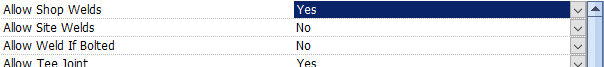
Weld standard - Choose the weld standard ISO or ANSI (AWS)
Allow shop welds - When enabled parts within the same assembly can get welds between them
Allow site welds - When enabled parts not in the same assembly can get welds between them
Allow weld if bolted - When enabled parts bolted to each other can get shop or field welds between them
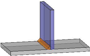
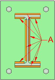
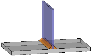
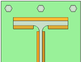
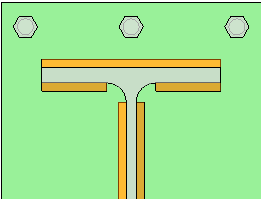
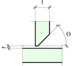
Allow Tee joint - When enabled welds can be created for Tee joint situations

Example of a tee joint
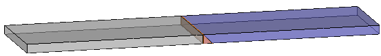
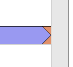
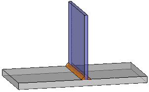
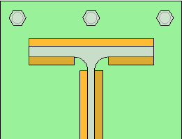
Allow Butt joint - When enabled welds can be created for Butt joint situations

Example of a butt joint
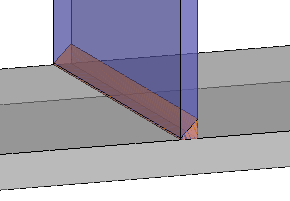
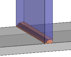
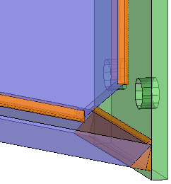
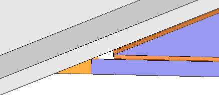
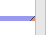
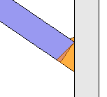
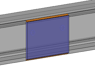
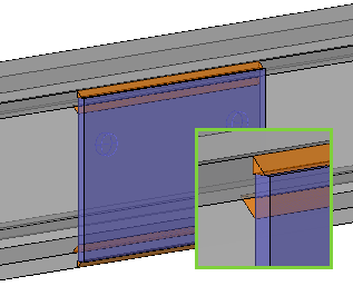
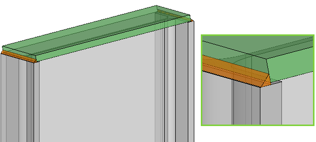
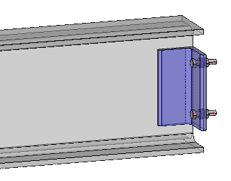
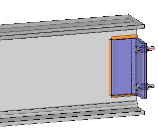
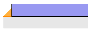
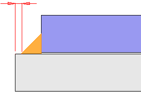
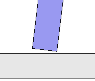
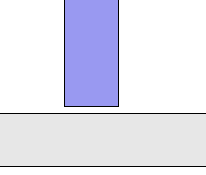
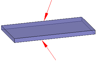
Allow Touching by edge - This setting allows enabling or disabling welds for situations where two parts have no full contacting surfaces to weld, but are still (nearly) touching with an edge of one part (or two edges in the case of butt joints). These skewed joint situations also have other related settings and overrides to influence weld type and behavior
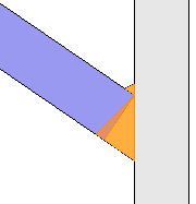
In this example, the blue plate is touching the arriving face with an edge only. A Bevel groove with a backing run is drawn here.
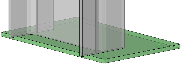
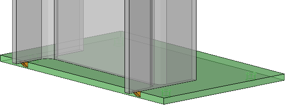
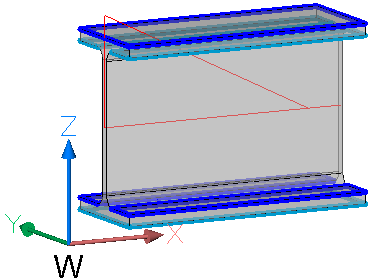
Allow weld on both plate faces - If this is enabled then double fillets, double bevels, etc can be drawn. If it is disabled then only a single side will be welded (unless other settings force the other side, such as a bevel+backing run)
For fillets an example application of single sided welds are base plates with light column loads.
For bevel welds a single side is usually beveled for thinner plates, and both sides for very thick plates. This is defined by settings in the overrides
|
|
Example of both plate faces being welded |
Example of only one plate face being welded |

Allow groove on both plate faces - As above, but this applies only to groove welds, not fillets. The main use for this setting is to avoid double sided groove welds in uneconomical and impractical situations.
|
|
|
An example where grooves on both plate faces was enabled. Two groove welds could be drawn if this is desired. |
An example where grooves on both plate faces was disabled. When a thin plate is welded, then a groove weld on just 1 side is usually desired. |
An example where grooves on both plate faces was disabled. The backing run can be added easily by choosing a Tag Style with backing run or other backing type enabled. |
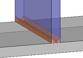
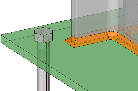
Allow far side weld overwrite - When you enable this option, then it will be possible to override the far side of the weld with specific settings, for example a backing run. This setting will cause the 'other side' weld of the current Tag Style to take precedence over the weld assigned to that side by other settings (ex: an other side fillet weld may be replaced by a backing run when the tag style is a Bevel Weld with backing run)
In some geometric cases like this one a backing run or other type of backing is usually preferred over a full fillet weld on the other side of the bevel.
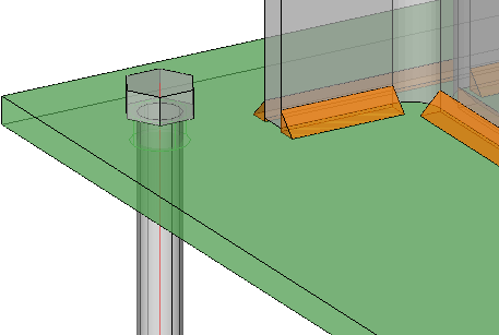
Prefer as arrow side - It may happen that there are conflicts between the 2 welds on opposite sides of the same plate (a conflict may be that one setting asks for a different type of weld on one side than on the other side). When this option is enabled, the arrow side will take preference above the far side. For example in skewed joints we generally assign the larger angle as the arrow side. On beam flanges we assign the side pointing to the outside of the beam is assigned as arrow side.
To make it possible to automatically draw this weld, the Prefer as arrow side was activated for the larger angle between the welded parts in an override. In the override topic, the filter being used for this is called Plate angle min/max.
Always merge weld sides on tag - Front & back welds of a plate are by default modeled using the same arrow side on the tag, if both sides are equal. Enabling this settings forces more double-sided tags.
Disabling this makes manual modification easier but sacrifices flexibility. Enable this option if you want to have the flexibility of being able to set different sizes for each side.
Use with care; this option does not work well in combination with the all-around setting of the weld tag or other settings that enable welds on plate edges or on member section fillets, because those welds have no other side counterparts.
- This is an example result when using the Always merge weld sides on tag disabled : the 8 weld segments are all drawn in a single weld object all using the arrow side. In shop drawings these welds may still be automatically grouped into arrow side / other side symbols to reduce clutter.
- This is an example result when using the Always merge weld sides on tag enabled : the 8 weld segments were drawn with the help of both arrow side / other side, allowing more control over the weld sizes. In shop drawings the corresponding weld symbols will likely be similarly grouped.
Swap bases for butt joints - This option only works on butt joints, and gives you control control over which side is beveled.
|
|
A possible scenario where the blue plate is beveled |
When enabling the Swap bases for butt joints option, the other plate is beveled in this scenario |


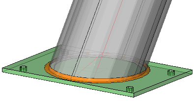
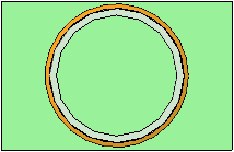
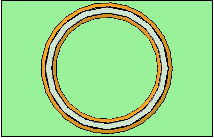
Allow weld inside section - When enabled welds inside hollow sections can also be created
|
|
The result when this option is disabled for a CHS profile |
The result when this option is enabled, the CHS is also welded on the inside |
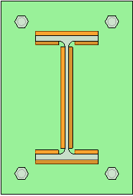
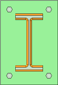
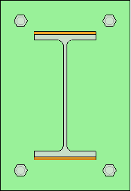
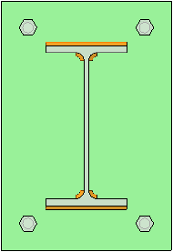
Allow weld on section fillet - When enabled all the section fillets of members like I/Channel/Angle shapes can also get welds
|
|
The result when this option is disabled for an I shape profile |
The result when this option is enabled for an I shape profile |
Allow weld on section fillet if standalone - When disabled, then standalone fillet welds will not be drawn. This situation can occur when not all plates are welded. In almost all situations it is best to turn this option off.
|
|
The result when this option is disabled for an I shape profile |
An undesirable result when this option is enabled and welds on fillets are also enabled, while the other welds may be skipped for other reasons. |
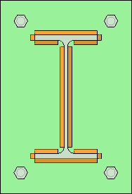
Allow weld on plate edge - When enabled the edges of plates such as flange toes will also be welded.
|
|
The result when this option is disabled for an I shape profile |
The result when this option is enabled for an I shape profile : the flange toes are also welded. Note that to get this result some overrides were removed. |
Allow weld towards member - Enable this to allow the weld facing the inside of a member (this will result in welds that are difficult to access)
|
|
The result when this option is disabled for a toe plate. In the default settings this result is achieved by certain overrides. |
The result when this option is enabled for a toe plate : the hard to access side is also welded. Note that to get this result some overrides were removed. |
Allow tee joint between plate faces - A plate face is the top or bottom face any plate. A plate may be part of a more complex object, for example a plate could also be the web or flange of a member.
Each fillet leg is on the top or bottom face of a plate. Welds between plate faces are the most common tee joint case : baseplates, endplates, stiffeners, ...
This should usually be enabled except in certain cases. Here are some example when these welds should be skipped :
- When the back side of a toe plate is welded, which is hard to get to
- When the angle between the plate faces is too big or too small.
|
|
The result when this option is disabled for stiffeners |
The result when this option is enabled for stiffeners |
Allow tee joint between plate edges - Plate edges are faces along the thickness a plate, including flange toes and the two ending faces of a member. This setting can disable creation of welds between two plate edges.
An example of a tee joint between plate edges. This is in fact a corner joint type, but AutoWeld considers the individual Tee joint situations on each side of the joint, not the overall joint situation.
In this example, the edge face of the profile's flange is the continuous arriving to surface. The edge face of the end plate is the arriving or ending face.
Allow tee joint between plate edges if not aligned - Plate edges are faces along the thickness a plate, including flange toes and the two ending faces of a member. When two plate edges are not aligned to each other (not parallel), then the need for a weld is unlikely. This option allows us to disable the creation of welds in this situation.
If this option is enabled, it could trigger the creation of undesirable small welds on the sides of plates.
|
|
An example of the result when this option is disabled |
An example of the result when this option is enabled |
Allow tee joint for overlapping plates - This option allows you to enable or disable welds for lap joints. Examples of overlapping plates are welded cleats, welded clip angles and web or flange doubler plates.
|
|
The result when this option is disabled for a clip angle |
The result when this option is enabled for a clip angle |
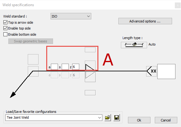
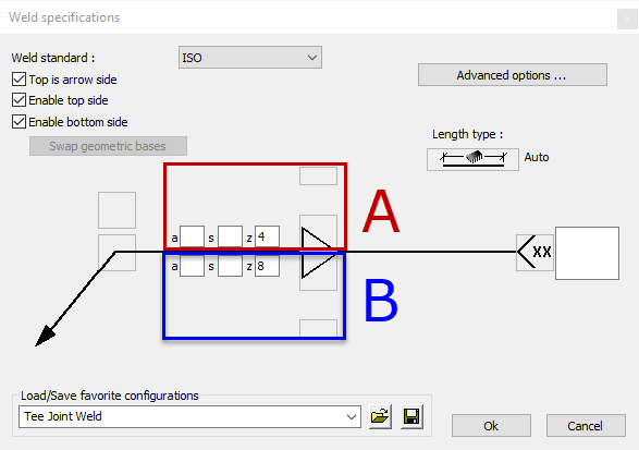
Tee joint weld tag name and Butt joint weld tag name: Choose the weld configuration to be used for Tee joints.
You can review, modify and add new weld styles here directly.
This will bring up the Weld Symbol dialog that allows you to modify the weld style with the help of a weld symbol drawn on the dialog.
Note that you are modifying the settings of the 3D weld, the 2D weld symbols are drawn later when shop drawings are generated.
Some properties of this style may eventually be overridden by other rules, see lower in this topic.
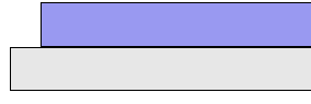
Size by thinnest plate - Enable this if you want the fillet size of the weld to be dictated by the thickness of the thinnest plate of the 2 joined parts. This option applies to fillet welds only, and is usually enabled. The fillet leg size table uses this thickness to determine the weld size (see next setting).
|
|
The result when this option is disabled : fillet size is determined by the thickest plate |
The result when this option is enabled : fillet size is determined by the thinnest plate |
Prefer design throat - When enabled, all of the created welds will have the design throat size set.
This is the same as the nominal throat size (a for ISO).
When this option is disabled, all of the created welds will have the leg size set (z for ISO).
All of the weld size tables have a column for throat size and one for leg size. The column that applies to this setting will be used.
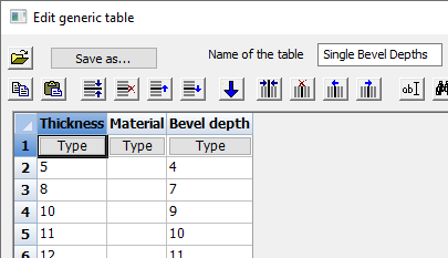
Fillet leg size table - This table lets AutoWeld match plate thickness to a weld size. The first row with thickness that is equal or larger and with matching material is selected and the corresponding weld size is used.
You can review, modify and add new size tables here directly :
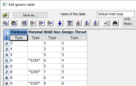
The rules for this table are :
- The table needs to contain at least 2 columns : the first containing the plate Thickness, and the other containing the Weld Size.
- The thickness and all the weld size columns need to be of type Distance. By default weld size will be the fillet leg size (z for ISO).
- It is also possible to have a column with the design throat size (a for ISO) of the weld. The column name needs to contain the word Throat.
This column will then be used automatically when the option Prefer design throat is enabled. This setting is located just above the size table settings. - The optional column Material can also be used. This column needs to contain the word Material and should be of type String.
This column will work as an extra filter besides the plate thickness :
When the field is empty, then the material filter is effectively disabled for the thickness of that row.
When the field contains text, then this text should be a match with the material property of the part. Otherwise the row will be skipped.
Instead of doing an exact text match we can also use wildcards in the text.
If we use the text *S355*, then the material should contain S355, but other letters may precede or come after S355 in the part's material property.
Bevel depth table - This table lets AutoWeld match plate thickness to a bevel depth. The first thickness that is equal or larger and with matching material is selected and the corresponding bevel depth is used.
You can review, modify and add new size tables here directly :
The rules for this table are :
- The table needs to contain at least 2 columns : the first containing the plate Thickness, and the other containing the Bevel Depth..
- The Thickness and Bevel Depth columns need to be of type Distance.
- The optional column Material can also be used. This column needs to contain the word Material and should be of type String.
This column will work as an extra filter besides the plate thickness :
When the field is empty, then the material filter is effectively disabled for the thickness of that row.
When the field contains text, then this text should be a match with the material property of the part. Otherwise the row will be skipped.
Instead of doing an exact text match we can also use wildcards in the text.
If we use the text *S355*, then the material should contain S355, but other letters may precede or come after S355 in the part's material property.
Skewed Tee factor table - This table tells AutoWeld to increase or decrease fillet leg size depending on the angle of the skewed parts. This is done by retrieving a factor.from this table : When the factor is 0.5, the normal weld size is halved.
Note that fillet leg sizes are measured perpendicular to the welded surfaces, as if using a fillet gauge.
You can review, modify and add new size tables here directly :
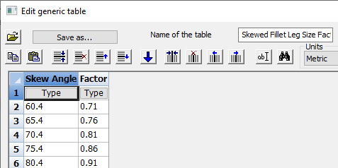
The rules for this table are :
- The table needs to contain the column named Skew Angle (type Angle Degrees)
- The table needs to contain the column named Factor (type Distance).
Z loss dimension - Fillet welds in skewed T-joints sometimes need a Z-Loss dimension added to the throat size. This should be set by overrides.
The settings Shrink fillet size for free space, Minimum fillet size for free space and Minimum offset to free edge after shrinking work together to allow the reduction of the weld size depending on the available space:
- Shrink fillet size for free space - When enabled and there is not enough space for the weld that would be drawn, the weld size will be shrunk to make it possible to add the weld. This is an example of a location where there is not enough free space to create the weld. Enabling this option will make creation of this weld possible :
|
|
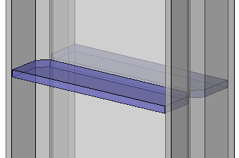
When this option is disabled: not enough space to weld |
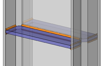
When this option is enabled: the reduced-size weld is created |
- Minimum fillet size for free space - The weld size of the shrunken weld does not go below this value. If it does, the weld will not be created.
- Minimum offset to free edge after shrinking - When the weld is being shrunk, this offset from the free edge will prevent material melting at the edge :
Offset from the free edge
Add root gap to fillet leg size - When enabled the root gap between the 2 joined parts will be added to the fillet leg size.
The root gap is the situation of the to be joined parts before any weld preparation is being done.
This option is especially useful for skewed Tee joints.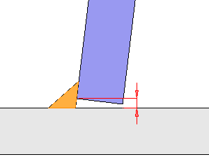
An example of the root gap between the to be joined parts
The settings Unify fillet sizes between 2 parts and Maximize fillet size on unify work together, they allow you to make sure the weld segments between two parts all have the same sizes even they are on a member with plates of different sizes.
- Unify fillet sizes between 2 parts - Enable this to make sure that all the welds have the same size. It is useful when an all-around weld is needed on a part with varying plate thickness (for example, the different thickness of web and flange of a I shaped member). This is not applied to fillet welds on plate edges when the weld is aligned with the plate edge
- Maximize fillet size on unify - Determines if the largest or smallest fillet size is chosen when fillet sizes are unified. This is usually the safer option
These 3 examples illustrate the 2 unify settings :
|
|
|
Unify fillet sizes disabled : the flange and web may get different weld sizes |
Unify fillet sizes enabled and Maximize fillet size enabled : the flange and web get the same weld sizes (the biggest one) |
Unify fillet sizes enabled and Maximize fillet size disabled : the flange and web get the same weld sizes (the smallest one) |
Note: in this example the setting Size by thinnest plate was disabled to make the above 3 examples possible. Otherwise the base plate's thickness was used for determining the weld size. This demonstrates how results may vary in different situations.
Layer name - All of the 3D welds drawn by this command will be set on this layer name
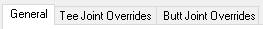
Tee Joint Overrides and Butt Joint Overrides tabs
The Tee joint and Butt joint override tabs are similar. They both contains overrides, but the overrides have been split up by joint type for convenience.
The purpose of these overrides is to allow automatic weld creation fine-tuned to very specific situations. In essence this list will override the weld creation settings in the situations that are filtered for in each entry.
A simple example of the override system is when a different weld size table is assigned for welds between specific types parts. For example the overrides that set the weld size table for base plates, end plates, stiffeners, etc...
Each entry in this list is an override for a specific situation. The row contains only a part of the filters and settings of the override. The rest of the settings of the entry are accessible through the  and
and  buttons.
An override entry has 2 important aspects that determine what it does :
- Filters : The rules to which the parts and weld joint need to comply. If one of the filters did not pass then the override does not apply to that situation and is skipped.
- Overrides to set : The settings that should be applied to this joint situation when the filters were all passed successfully.
Both of these are explained in detail lower in this topic.
The arrangement of the override entry is of importance : AutoWeld will process entries in the list from top to bottom.
If the weld joint situation matches with all active filters of an override, then that entry's overrides will be applied. The next entries will still be processed after that, unless an override is being applied that has the setting All are final enabled.
If the setting Current is final is enabled, then only the settings overridden by the current override are final, but not the other weld settings so AutoWeld will keep processing other entries to complete the non-finalized settings.
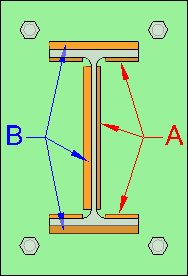
Important: Each joint being processed for welding considers one surface of one part versus one surface of another part. This means that in typical plate vs plate situations there will be two joints processed in a separate run: one on each side of the plate.
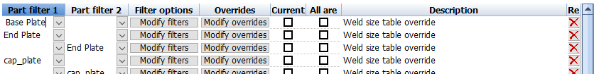
This is a clarification of each column in this list :
|
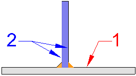
|
'Arriving to' part 1 and 'Arriving' part 2 for Tee joints |
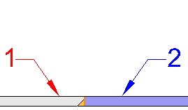
Beveled part 1 and non-beveled part 2 for Butt joints |
Part filter 1 - For Tee joints this is the continuous part to which the other (ending) part is arriving to. For Butt joints this is the part that is beveled when only one part is beveled.
Part filter 2 - For Tee joints, this is the ending part that is arriving at the continuous face of part 1. For Butt joints this is the part that is not beveled when only one part is beveled.
Filter options - Use the button to review or modify all of the filter settings of this override. See below for more information about all of the settings in this dialog.
Overrides - Use the button to review or modify all of the overridden settings of this override. See below for more information about all of the settings in this dialog.
Current is final - When this is enabled and the override is being applied then only the settings overridden by the current override are final, but not the other settings so AutoWeld will keep processing other entries to complete the non-finalized settings.
All are final - When this is enabled and the override is being applied then all of the settings for this joint are final. The list of overrides will stop being processed for this joint.
Description - This description was added for convenience only, to provide a summary of each entry when desired.
These are the purposes of the buttons next to the list :
 Pressing this button will open the Reset AutoWeld settings dialog. It is almost the same as the main reset button at the top of the dialog, except this will only reset the override lists, and not the settings on the General tab.
 Pressing this will move the current row up.
 Pressing this will move the current row down.
 Allows you to add a new override row to the list.
 Allows you to copy the currently selected override row.
 Allows you to delete the currently selected override row.
Override filters
When clicking on the button of an override, you can review and change all of the filters of the override.
When one of these filters are not met for a certain situation, then the override is skipped entirely for that situation.
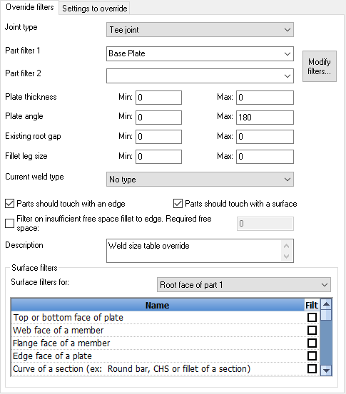
This is an explanation for all of the filter settings :
Joint type - Choose the joint type, Tee or Butt, to which this override should apply.
|
|
'Arriving to' part 1 and 'Arriving' part 2 for Tee joints |
Beveled part 1 and non-beveled part 2 for Butt joints |
Part filter 1 - For Tee joints this is the continuous part to which the other (ending) part is arriving to. For Butt joints this is the part that is beveled when only one part is beveled. Leave this empty to skip the filter.
Part filter 2 - For Tee joints, this is the ending part that is arriving at the continuous face of part 1. For Butt joints this is the part that is not beveled when only one part is beveled. Leave this empty to skip the filter.
Plate thickness min/max - Enter the minimum and/or maximum thickness of the plate. This applies to all types of plates including a flange or web of a member. If both minimum and maximum are set to 0 then the filter is disabled.
Plate angle min/max - Enter the allowed minimum and maximum included angle between the plates on the side of the joint. If both minimum and maximum are set to 0 then the filter is disabled.
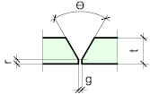
Existing root gap min/max - Enter the minimum or maximum root gap that is allowed between the 2 parts. This existing root gap is not set by the 3D weld itself. It is retrieved from the parts that are to be welded together. If both minimum and maximum are set to 0 then the filter is disabled.
|
|
'r' is the root gap in this tee joint |
'g' is the root gap in this butt joint |
Fillet leg size min/max - If you want this override to only work on welds with a certain fillet size, then set the minimum and maximum here. If both minimum and maximum or set to 0, then the filter is disabled. Overrides using this filter should be used after overrides that determine the fillet weld size.
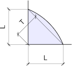
L on this image is the leg size
Current weld type - If you only want this override to apply to a particular weld type only, then select it here. If you set this to No type, then the override will be used on all weld types. Overrides using this filter should be used after overrides that determine the fillet weld type.
Parts are touching with an edge - Enable if you want the override to work on parts that are not touching with a surface, but are (nearly) touching an edge
Example of 2 parts touching with an edge to a face
Parts are touching with a surface - Enable this if you want the override to work on parts that are touching each other with a surface
Example of 2 parts touching with their surfaces
Filter on insufficient free space to edge, required free space - Enable this if you want this override to only apply to cases where there is not enough space for the weld. You could then use this override to automatically reduce the weld's size, or skip the weld entirely.
The required free space that should remain after the weld is added in this lap joint example
Description - This description was added for convenience only, to provide a summary of each entry when desired.
Surface filters for - Use this list to filter based on the types of side and root faces of the welded parts.
|
|
The faces of a Tee joint, with each side of part 2 treated as a separate joint by AutoWeld |
The faces of a Butt joint, with each side the plates treated as a separate joint by AutoWeld |
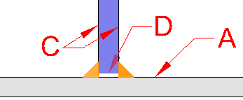
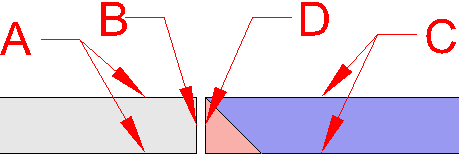
A = Side face(s) of part 1
B = Root face of part 1
C = Side face(s) of part 2
D = Root face of part 2
The Root face of part 1 does not exist for Tee joint types.
Note again that in AutoWeld logic, the flanges and the web of a member are also considered individual 'plates'
When you select one of these surfaces in the dropdown, the list below will show all the geometric filters that can be activated for that face.
These are all the different surface types that can be used as filters per face :
- Top or bottom face of plate - These are the largest faces of a plate object :
- Web face of a member - This refers to the web faces of an I shape or channel profile
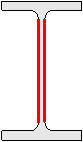
The web faces of the member are highlighted in red - Flange face of a member - This refers to the flange faces of an I shape or channel profile
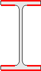
The flange faces of the member are highlighted in red - Edge face of a member - This refers to the edge faces of plates in the section.
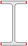
The edge faces of the member are highlighted in red - Curve of a section - This refers to any curve in the section of a member
- Fillet of a section - This refers to the fillets between 2 straight edges in the section of a member :
The fillet surfaces of the member are highlighted in red - Hole in a section - This refers to the hole geometry that makes CHS and RHS sections hollow
- All surfaces on the extrusion side of a member - All surfaces of a member except the ending and starting surface, and except all cut surfaces.
- Member end - This refers to the end plane of a member (can also be cuts at the end of the member)
- Any type of cut - This refers to any of the cut types that can be drawn with Parabuild (For all available types, see Add Cut to Macro)
- Other topology - These are the faces that remain if we exclude all plate sides, plate faces, fillets, cuts, and member ends.
- Faces on the extent of the section - This refers to all of the faces that are touching the outer extent box of the section :
The faces on the extent of the member's section are highlighted in red - Faces NOT on the extent of the section - This refers to all of the faces that are not touching the extent box of the section :
The faces not on the extent of the member's section are highlighted in red - Face in +-XYZ direction of part - These are the faces that follow one of the directions of the part's ECS.
ECS stands for Element Coordinate system.
For profiles the X direction of the Ecs is the axis line, the Y direction is the small side of the profile's triangle, and the Z direction is derived from these X and Y directions.
This is an example of what the directions of a profile's Ecs faces can be :
|
|
|
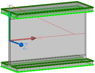
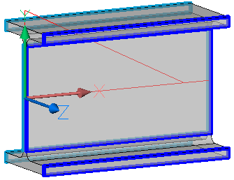
The Ecs +X faces are highlighted in red, the -X faces are highlighted in orange |
The Ecs +Y faces are highlighted in green, the -Y faces are highlighted in light green |
The Ecs +Z faces are highlighted in blue, the -Y faces are highlighted in light blue |
- Face in +-XYZ direction of world - These are all the faces that are parallel to one of the World directions of the 3D drawing.
This is an example of what the directions of a profile's faces can be when they are translated to the world coordinate system :
|
|
|
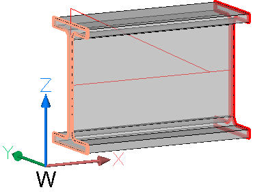
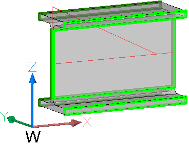
The World +X faces are highlighted in red, the -X faces are highlighted in orange (coincidentally the same as ECS X directions in this case) |
The World +Y faces are highlighted in green, the -Y faces are highlighted in light green |
The World +Z faces are highlighted in blue, the -Y faces are highlighted in light blue |
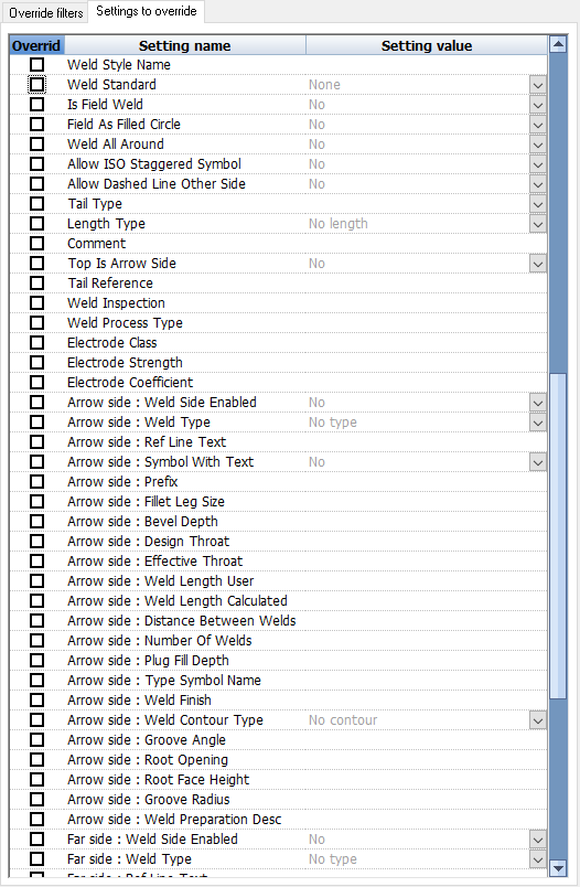
Settings to override
When clicking on the button of an override entry, you can review and change all of the settings that can be overridden.
All of the settings in this list that are enabled will be applied to each weld joint occurrence that has passed all filter rules.
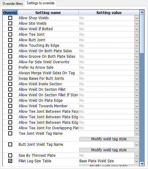
Each row in this list represents a setting that can be overridden by this override rule.
This list contains the following columns :
Override is enabled - When enabled this setting will be overridden to the value set in the last column.
Setting name - The name of the setting that should be overridden
Setting value - The value that should be used for the setting. This value can only be changed when the override of this setting is enabled. When it is gray, the setting will not be overridden and so will not be applied by the override.
The options in the beginning of the list are the same as those on the General tab. Default settings can be overridden here for specific situations.
Below those settings it is also possible to override any of the individual properties of the 3D weld :
You can find more information about these 3D Weld properties here.