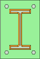
3D Weld
The 3D weld object has the following property categories:
Arrow side / Back side
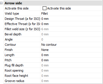
Both sides of the weld tag have the same properties, so they are listed just once.
Activate this side - When this side is active, the weld will be drawn on this side of the material.
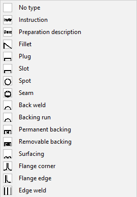
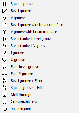
Weld type - These are all the available weld types. Not all have 3D volume representations:
|
|
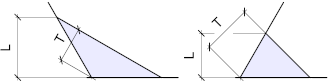
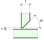
Design throat (a for ISO) - This option only applies to Tee joints. It is the distance from root edge to the weld surface.
Design throat is the same as nominal throat size (a for ISO).
The design throat size is T on this illustration
Effective throat (s for ISO) - The effective throat is only a setting that is stored and shown in the weld symbol and/or reports. Parabuild does not use this value during the modeling process.
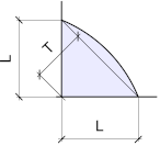
Fillet weld size (z for ISO) - This size only applies to fillet welds. In skewed joints this is not the same as the leg length. Measurement is similar to the use of a fillet gauge:
|
|
L on this image is the weld size for a square joint (it is the same as the leg size in this case) |
L on this image is the weld size for skewed joints (obtuse and acute) |
Bevel depth - This option only works on these weld types : Bevel grooves, V Grooves, J Grooves, U grooves and Bevel Groove with Fillet.
The default is to set the bevel depth, but you can also set the bevel depth to 0 and then set the Root face height instead. Then Parabuild will use the Root face height size to calculate the bevel depth automatically.
|
|
Bevel depth is t-r in this single V weld |
Bevel depth is (t-r)/2in this double V weld |
Angle - For groove welds, this is the groove angle.
For plug welds, this is the countersunk angle.
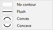
Contour - The contour can be flush, convex or concave :
Finish - The finish option is only available when the AWS standard was chosen as the standard for the weld.
These finishing types are available : 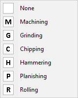
Length - This option will only work when the Length type property was set. When the length is not set, the weld length will be the distance between 'abrupt ends' of the weld edge.
Pitch - For AWS : This is the center-to-center spacing of welds for intermittent welds
For ISO : This is the offset spacing between welds for intermittent welds
Plug fill depth - This option only works on slot and plug welds. It is the depth of the weld material that should be filled in the slot.
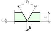
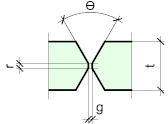
Root opening - The root gap is not set by the 3D weld itself. It is retrieved from the parts that are to be welded together.
|
|
'r' is the root gap in this tee joint |
'g' is the root gap in this butt joint |
Root face height - The is also called the 'landing'. It is the height of the face that is at the narrowest part between the welded elements. It is not drawn on the weld annotation and is only for reporting, weldprep, etc...
This value can also be extracted from the bevel depth. The default is to set the bevel depth, but you can also set the bevel depth to 0 and then set the Root face height here. Then Parabuild will use this size to calculate the bevel depth.
|
|
'r' is the root face height in this single V weld |
'r' is the root face height in this double V weld |
Groove radius - This is the root radius and only applies to J-Groove and U-Groove welds.
Miscellaneous
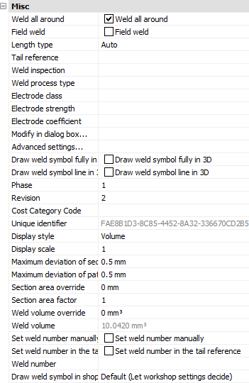
Weld all around - When you enable this property, then the weld all around symbol will be shown on the weld annotation on the shop drawing.
If you enable this option on a 3D weld, then the welded segments will be expanded automatically to make the weld all-around :
|
|
A weld with Weld all around disabled |
A weld with Weld all around enabled |
Field weld - This setting determines if the weld is a site or shop weld.
Length type - By default, the weld length is automatically determined. But you can enable a fixed weld length, an intermittent weld or a staggered weld here.
Tail reference - The text to be shown in the tail of the weld symbol
Weld inspection, Weld process type, Electrode class, Electrode strength, Electrode coefficient - These are information fields about the weld for tracing and to show in reports.
Modify in dialog box - This will open the weld in a dialog box that visually represents the weld symbol
Advanced settings - This will open the advanced visual settings for the weld, which are text height, arrow size, tail size, etc...
Draw weld symbol fully in 3D - Adds the full weld symbol to the 3D representation
Draw weld symbol line in 3D - Adds a weld line and type symbol to the 3D representation of the weld
Phase - The phase in which this weld needs to be produced
Revision - The revision of the weld - currently not in use
Cost Category code - These codes are usually determined while a quote for the project is made. This code can then later be assigned to the 3D model when the project was ordered. This way the parts can be traced from estimation to production and to completion inside ERP/MIS software.
Unique identifier - Each weld object will receive a unique number during numbering, this number can be used to track welds.
Display style - Choose one of the display styles for the 3D weld : None, Axis, Wireframe or Volume. Axis or none is the least taxing on computer resources, volume will be the most taxing for large projects.
Display scale - When the weld symbol is also drawn in 3D (see 6 properties higher), then this display scale will determine the size of the weld symbol.
Maximum deviation for section - Curved geometries are therefore drawn segmented to reduce graphics overhead. Enlarging this number will decrease the accuracy of the drawn weld but may result in faster graphics for large projects.
Maximum deviation for path - Curved geometries are therefore drawn segmented to reduce graphics overhead. Enlarging this number will decrease the accuracy of the drawn weld but may result in faster graphics for large projects.
Section area override - Enter a value here if you want to specify a different section area for the weld than the one calculated by Parabuild. The section area influences the weld volume and weight calculations.
Section area factor - Allows you to increase or decrease the section area calculated by Parabuild. Enter for example 2 if you want to double it, or 0.5 if you want to halve the calculated area. The section area influences the weld volume and weight calculations.
Weld volume override - Enter a value here if you want to specify a different volume than the one calculated by Parabuild. This may be useful for weld types that have no 3D representation.
Weld volume - The weld volume as calculated by Parabuild.
Set weld number manually - To specify the number manually instead of having it automatically assigned by weld numbering
Set weld number in the tail reference - This will cause the weld number to be displayed in the tail of the weld symbol
Weld number - This field can be filled automatically by the Number welds command
Draw weld symbol in shop drawing - This property will determine whether this weld will get a weld symbol drawn for it in the assembly shop drawing.
It has the following options :
- Default (Let workshop settings decide) - The workshop drawing settings will determine whether this weld receives a weld symbol You can learn more about these settings in the Weld symbols on shop drawings topic
- Never skip, regardless of workshop settings - The workshop drawing settings will be ignored for this weld
- Always skip - The weld will never receive a weld symbol in the shop drawing