Weld symbols on shop drawings
Parabuild will automatically draw weld symbols on the assembly shop drawings for the welds that were drawn in 3D.
There are settings to skip or merge certain weld symbols so that the assembly drawings are not cluttered with weld symbols.
The following settings are for influencing how and when the weld symbols are drawn on the 2D drawings :
- It is possible to disable the weld symbol individually per 3D weld.
You can find this setting in the properties panel of the 3D Weld.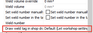
- The above property can also be changed using overrides in the AutoWeld command.
By changing the property here, one can automatically disable weld symbols for certain 3D welds :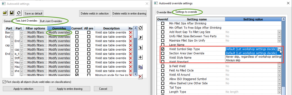
- Each 2D view in the workshop drawing settings has an option that can be used to disable the automatic addition of weld symbols on that view.
By disabling this setting for all the different 2D view types, one could effectively disable the drawing of all weld symbols.
However this setting can also be used to confine weld symbols to certain views, for example only on side views.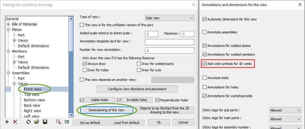
- In the Sheet settings, there are several options available that allow you to skip the annotation of common or repetitive weld symbols :
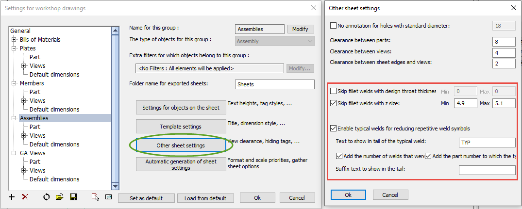
The following options are available for this purpose : - Skip filet welds with design throat min/max - Enable this to hide all fillet welds whose design throat are within the given minimum and maximum sizes.
Design throat is the same as nominal throat size (a for ISO). - Skip fillet welds with fillet size min/max - Enable this to hide all fillet welds whose fillet leg size ('z' size) are within the given minimum and maximum sizes.
- Enable typical welds for reducing repetitive weld symbols - Typical welds are identified as welds with the same sizes and type that are also welding together geometries with the same part numbers. By enabling this identical welds can be represented by a single typical weld symbol with an added automatically generated tail description.
- Text to show in tail of the typical weld - Enter the typical weld identifying text that should be added to the tail, so that the weld symbol can be recognized as such
- Add the number of welds the symbol represents in the tail - When you enable this, the total number of parts that should be welded using this typical weld symbol will be added to the weld tail
- Add the part number to which the typical weld points to in the tail - When you enable this, the part number of the welded part will be added to the tail (the part number of the stiffener in our example)
- Suffix text to show in the tail - Enter the optional extra text that should be added after the part count and part number in the tail.