The 3D Weld object
The 3D weld object represents the welding that needs to be performed between 2 parts.
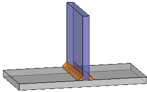
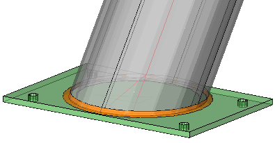
The 3D weld (orange) is visualized approximately to how the weld would look like when finished
3D welds can be drawn in 3 ways :
- Automatically using the AutoWeld command
- Automatically with the help of macros. See the Welds tab inside the review Macro for more information about this method
- Manually using the Draw welds option in the context modeler
Users can also edit existing connection templates (or create new ones) with all welds completed to their preferences. Upon applying the connection between members, the welds are copied along with the rest of the connection objects and will be recalculated to fit the new members. Fine-tuning the templates of frequently used connections in this way can save the detailer additional time while modeling.
Modeling welds in 3D is useful in multiple ways:
- The estimation of a project : knowing how many welds will need to be made, the length and size of the welds, and how material will be spent on them, can be useful for composing a project quote.
- Optimization: quickly generating welds for the whole project allows the user to cost-optimize a project by comparing different project permutations. In the same way AutoWeld can be used to compare the cost of different connection options.
- 3D welds will automatically receive Weld Symbols on the assembly shop drawings. This is a practical way to indicate weld requirements that fall outside of the company's standard welding rules on the shop drawing.
- Visualization of welds will aid the user in determining problematic welding situations and wrongly sized welds
- Some industries or companies require each weld to be annotated on shop drawings, regardless of company weld standards or rules.
- In shop floor planning stages it is useful to know which assemblies require significant welding so that their component parts may be produced sooner.
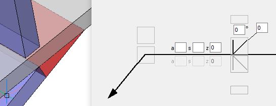
You can double-click a 3D weld to review or edit the weld's settings in a visual dialog box.
You can also use the AutoCAD/BricsCAD properties panel to review or edit one or multiple 3D welds at the same time.
You can find a full breakdown of the all the properties of the 3D weld in the 3D Weld properties topic. Each property is explained in this topic.
Options and behaviors specific to bevel welds
Here are some behaviors that are specific to bevel welds that you need to be aware of :
- The bevel weld has a root face height setting that will work when the weld size is 0.
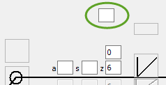
- A bevel weld with size 0 means that the size will be automatically determined (Plate thickness minus the Root face height)
- The root opening should be the desired gap between the materials at the closest point.
When you set the root opening to 0, then Parabuild will try to find the existing root opening from the 3D model automatically. You can set the root opening to -1 if you do not want Parabuild to find the root opening automatically. A root gap larger then the gap in the model implies additional weld preparation. - When the angle of the bevel weld is set to 0°, and there is an oblique opening, then the existing opening will be filled without an additional beveling of the part.This example shows this case :