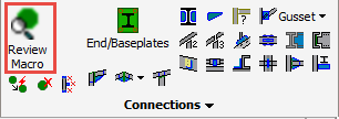
Review Macro
Command - PrB_DlgMacro
Using this command you can review and edit multiple macros.
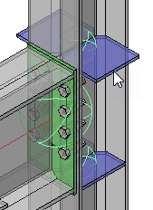
Here you may select one macro sphere using the mouse pointer, or any number individually, or using a frame.
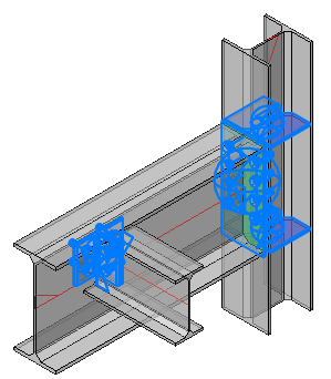
A Macro is identified by a sphere, which is a collection of geometric rules that holds the 'intelligence' of the elements making up the connection.
When a base profile of a connection is modified, the rules in the sphere will ensure that the elements in that connection adapt automatically to whatever modifications are made.
Reviewing macro using double-click
This command can also be accessed without the use of the icon.
When double-clicking a macro or a part, the corresponding macro will be opened in the Review macro dialog box.
More advanced options are available by pressing the SHIFT and/or CTRL keys while double-clicking, this will change the behavior of the action.
These are all the different behaviors, with an example drawing of what would happen when double-clicking a side rail :
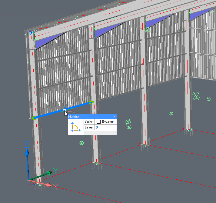
This is a Parabuild portal frame template that was fully parameterized, and we're double-clicking one of the side rails.
- Double-click without SHIFT nor CTRL pressed - Only the macro of the selected part will be reviewed. In the example, just the macro of the single side rail will be reviewed.
- Double-click with SHIFT OR CTRL pressed - All of the parts that are dependent on the same array will be reviewed. In the example the 4 side rails and the array itself will be reviewed.
- Double-click with SHIFT AND CTRL pressed - The top owning macro of the part that you selected will be opened, together with all of its sub-macros. In the example, the top owning macro is the portal frames macro so the entire drawing will be reviewed. That is because the entire drawing is fully parameterized.
The dialog box
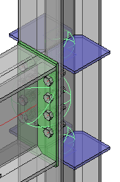
In this example we'll be working with a drawing fragment which is comprising of two connection types and two column web stiffeners.
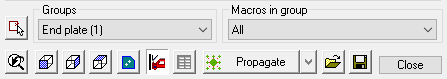
Clicking the Groups drop-down menu will show which macros have been captured by the selection (the number of each of the macros is shown in parenthesis).
Clicking on one of these macros will open the specific edit dialog (For more information on editing the dialog see the Review Macro dialog).
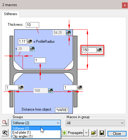
Should there be more than one macro in the selected group, any changes made will reflect in all macros within that group. An example, in this case, are the stiffeners.
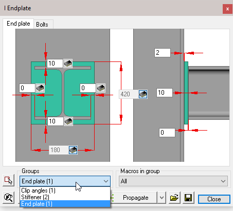
Select Stiffener (2) from the drop-down menu to open the edit dialog and change one of the dimensions, both of the stiffener macros will update
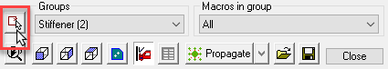
To change only one of the macros, click on the Select other macros button, and following the command line prompt: Select Entities.
Here you may select the stiffener macro sphere, or the stiffener itself and press <Enter>. Now edit the macro dialog as before, but this time only the selected macro will be updated.
This function will work with all macros.
The Macro edit dialog is available for all connections and will appear whenever a new connection is drawn.
Alternatively, the edit dialog may also be accessed by the Review macro command.
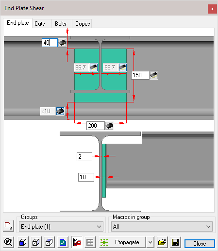
Each dialog is divided into 5 sections:
- The Title bar - which displays the current macro name (or the number of macros if more than 1 is being edited)
- The Tabs bar - which indicates the number of modules making up the macro. Selecting one of the tabs will open the appropriate edit dialog window. (Note! that the tabs will vary according to the selected connection type)
- The Dialog edit window - where the dimensions may be edited. This is explained in detail later in this chapter
- Bolts - (Under the Bolts tab) where you may select the bolt assembly and diameter from the drop-down menus
- The functions bar - where you may select, view, copy, and adjust macro settings. This will also be explained in detail later in this chapter.
The Dialog Edit Window
There are 4 different types of dimension controls:
- Switchable - This dimension type will be found where a dimensions is part of a string. Activating the switch will either enable or disable the dimension making it editable or responsive. A responsive dimension will automatically update when other dimensions in the string are changed.
|
|
Active |
Responsive |


- Active - an active dimension may be edited at any time

- Responsive - A responsive dimension is shown 'greyed' and cannot be directly edited, it will automatically update when other dimensions in the macro are changed, or when a dependent object in the drawing has changed. These dimensions are to be considered 'Reference dimensions'.

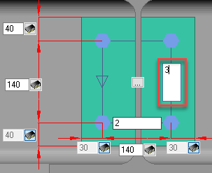
- Bolt spacing - These dimensions are found with bolt groups and can be identified by their elongated nature. There are two ways in which these dimensions are used. A single value will indicate the number of bolts to be equally spaced within the overall centers.
In the first example, there will be 3 bolts, equally spaced inside the overall centers of 140 (2 x 70)
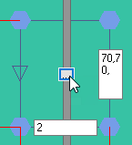
In the second example, the hole centers are specified separated by a comma (70 x 70). Any number of bolt centers may be specified.
This is particularly useful when the bolts are not equally spaced.


Pressing the button at the center of the section will open the Bolt pattern settings dialog, where you can perform the following actions:
The Functions Bar
Select other macros  Activating this command will prompt you Select entities, enabling you to modify a different selection set of macros.
Groups - The drop-down menu will list all the selected macros, the number in the (parenthesis) will indicate the number of selected macros in the group. Selecting a macro will open the macro edit dialog.
Any changes that you do in the dialog will be applied to all the macros within the group. If you wish to edit only one of the macros, use the Select other macro function below.
Macros in group - From the down menu you can choose to edit all macros in the group, or only one of the macros. This second list is therefore dependent on the group that you have selected: the list will be updated each time you select another group.
View buttons
 Restore original 3D view of the selected macro
 Front view of the selected macro
 Side view of the selected macro
 Top view of the selected macro
 Front view of the current part. This button will give you a view of the parts of the current module tab : If the Bolts module is active, you will see a top view of the bolts.
 When you modify a dimension of the connection, the complete connection will be checked for collisions. This icon works as a switch to enable or disable this automatic clash control. It can be useful to turn it off when you are editing many connections simultaneously and the clash control demands too much calculation time.
 This will execute the standards on the connection again. For more information about this see the chapter Standards for connections.
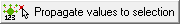
Next to the propagate button, there is a drop-down button that gives us access to a range of tools that will do something with the currently active macro(s) :
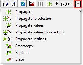
These are the purposes of all the tools :
 This tool will automatically copy the macro to all similar geometric locations in the drawing, potentially saving you a lot of time. For more information about this automation tool, see chapter Propagate.
 For more information about this automation tool, see chapter Propagate.
 For more information about this automation tool, see chapter Propagate.
 For more information about this automation tool, see chapter Propagate.
 For more information about this automation tool, see chapter Propagate.
 This tool allows you to copy the macro to other profiles. For more information about this tool, see chapter SmartCopy.
 This tool will replace the current macro with a new one from the library.
 This tool will erase the macro and all of it's components.

 With these tools you can save all values of the current selected connection(s) under a name and recall them at a later time.
Bolt Pattern Settings
This dialog comprises of 2 columns, the left hand column applies to bolts in the horizontal, while the right column applies to the vertical direction.
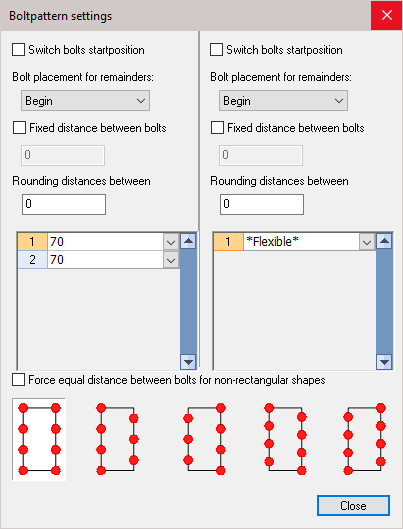
Switch bolts start position: Activating this check-box will reverse the order of the bolts, either from top to bottom, or side to side. This checkbox will only have an effect when the manual bolt spacing has been used.
Bolt placement for remainders: This option works in combination with the Fixed distance between bolts option because with it you stipulate at which side the remaining distance will be placed.
Fixed distance between bolts: The distance that you enter will always be respected.
Rounding distances between: This is an important option to avoid undesirable distances. Imagine that we have a pattern with a length of 100 mm. You choose 3 bolts for this pattern. The bolts are divided equal and as a result we get a distance between the bolts of 33.33 mm. Later that distance (rounded to 33 or 33.5) will be put on the workshop drawings, which is of course undesirable!
We avoid this by setting the rounding to 1 (or 5 or 10?). The distance between bolts is taken never smaller than the number that you enter here. Therefore with this option the bolts will never be drawn at distances of 33.33 but at distances of 33, or 35 or 30, depending on the rounding you choose.
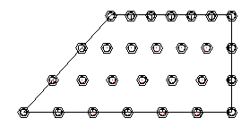
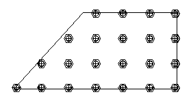
Force equal distances between bolts for non-rectangular shapes:
If you enable this option, the bolts that fall outside of the pattern will be removed.
|
|
Example with force equal distances disabled |
Example with force equal distances enabled |
Bolts
The bolt options are only available from the Bolts tab
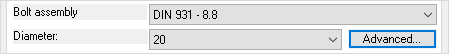
Bolt assembly - Select from the drop-down menu - The bolt assemblies can be configured, see chapter Bolt Assemblies
Diameter - Select one of the available bolt diameters from the drop-down menu
Advanced - Will open the Advanced bolt settings dialog - the settings entered here will only apply to the selected macro(s)
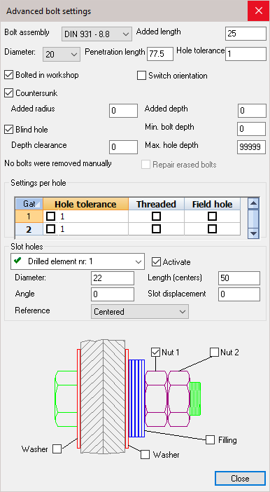
Bolt assembly - Select a new bolt assembly from the drop-down menu
Added length - increase the distance between the nut and the plate, the bolt length will increase accordingly
Diameter - Select a new bolt diameter
Penetration length - This length is calculated automatically : it is the total thickness of all the parts that are bolted together
Hole tolerance - Changes the bolt hole diameter. The value = Bolt diameter + Hole Tolerance
Bolted in workshop - Enabling this will make the bolt a shop-bolt, which will then be shown in the Position and Assembly sheet
Switch orientation - Enabling this will switch the orientation of the bolt - reversing the orientation of the nut and bolt-head
Countersunk - will change an ordinary bolt-hole to countersunk. This will enable the options to enter the countersink diameter and depth
Blind hole - This will change an ordinary bolt-hole to a blind hole. This will enable the options to enter the blind-hole depth.
Repair erased bolts - If a bolt was manually deleted, the prompt will read One or more bolts were removed manually. Checking this option will reintroduce the bolts.
Settings per hole - Here you can change the individual settings for the bolt-hole by selecting a new hole tolerance, making the hole threaded, and indicate whether its to be shop or site drilled.
Slot hole - Will change an ordinary hole into a slotted hole in one of the joined elements. Activating the checkbox will enable you to enter a hole diameter, slot length, the angle, and the slot displacement.
Finally - you can add or remove nuts, washers, and filling by checking or un-checking any of the checkboxes.
Drawing welds for the macro
When a new connection is drawn, it is possible to draw the welds for that connection from within this dialog box.
Each connection has a Welds tab for this purpose :
This dialog also allows us to choose a specific AutoWeld settings file that AutoWeld should respect for this macro and it's modules.
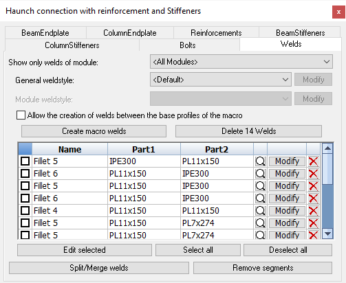
This tab dialog has the following options and actions :
Show only welds of module - The value that is chosen here will have an effect on several items in this dialog tab. The 2 main differences are :
When <All modules> is selected - In the list of welds in this dialog, all of the welds that relate to the macro are listed.
The action button Create macro welds will create welds for all modules in the macro.
The action button Delete xx welds will delete all welds that are related to the macro.
When a specific module is selected - In the list of welds in this dialog, only the welds that relate to the selected module will be listed.
The action button Create module welds will only create welds for the selected module.
The action button Delete xx welds will only delete welds that are related to the selected module.
General weld style - This setting is only available when <All modules> was chosen in the Show only welds of module dropdown box.
This setting has the following available options :
- <Default> - When Default is chosen, then this macro does not get special treatment for weld creation.
The AutoWeld settings that are currently active will be used to create the welds for this macro. - <No welds> - When No welds is chosen, then weld creation is effectively disabled for this macro.
The Create welds button will not create any welds for this macro, and also the AutoWeld command will respect this setting, and will not create any welds for the parts in this macro. - AutoWeld saved configurations - All of the AutoWeld styles that were previously saved in the AutoWeld dialog are listed here.
When you choose one of the AutoWeld styles here, that style will be used for welds in this macro, instead of the currently active AutoWeld settings.
Module weld style - This setting is only available when a specific module was chosen in the Show only welds of module dropdown box.
This setting allows us to override the weld style that should be used per module. When set, this takes preference over the macro weld style.
The setting has the following available options :
- <Default> - When Default is chosen, then the currently selected module does not get special treatment for weld creation.
The AutoWeld settings that are currently active will be used to create the welds for the currently selected module. - <No welds> - When No welds is chosen, then weld creation is effectively disabled for the currently selected module.
The Create welds button will not create any welds for this macro, and also the AutoWeld command will respect this setting, and will not create any welds for the parts in the currently selected module. - AutoWeld saved configurations - All of the AutoWeld styles that were previously saved in the AutoWeld dialog are listed here.
When you choose one of the AutoWeld styles here, that style will be used for welds in this module, instead of the currently active AutoWeld settings.
Allow the creation of welds between the base profiles of the macro - This option is only available when <All modules> was chosen in the Show only welds of module dropdown box.
This option should only be used on all-weld connections that do not draw plates or profiles, but that only draw endcuts and copes.
Normally, the weld creation routine would draw welds between the parts drawn by the macro themselves, and between macro-created parts and the base profiles of the macro.
But for weld-only connections, no parts are between the base members, they should be welded directly.
By enabling this option, the base members themselves will be analyzed and welds will be added to them if appropriate and allowed by the selected AutoWeld style.
This is an example of such as weld-only connection : 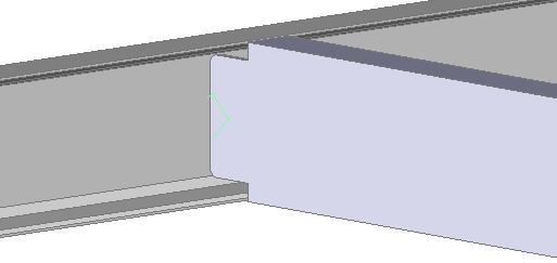
Create macro/module welds - By clicking on this button, the welds of this macro or the currently selected module will be created.
This is in effect the same as running the AutoWeld command, but here it is done selectively on this macro/module.
Do note that AutoWeld relies on classification in order to work optimally.
Automatic classification works best when the parts are finished and the relation between the parts is known: when the connections are finished.
Delete xx welds - By clicking on this button, the welds of this macro or the currently selected module will be deleted.
The list of welds - All the welds that are related to the macro or the currently selected module will be listed here.
Each weld is listed here as one row. Each row has the following information and actions :

 - Use this checkbox to activate the weld, so that you can edit multiple welds at once using the Edit selected button below
Name - This will show the type of weld and if has a size, it will also show the size of the weld.
Part 1 - This is the first part that the weld connects
Part 2 - This is the second part that the weld connects
 - This will zoom in on the weld in 3D. The 3D weld will also be selected at the same time.
Modify - This will open the Weld Symbol dialog box which allows you to change all of the 3D weld's settings. The 3D weld will also be selected at the same time.
 - This will delete the 3D weld object.
Edit selected - This will open the Weld Symbol dialog box which allows you to change the 3D weld settings of all the welds that are toggled in the above list. These 3D welds will also be selected at the same time.
Select all - This will check the checkbox of all the welds in the above list
Deselect all - This will uncheck the checkbox of all the welds in the above list
Split/Merge welds - This will open a separate tool that allows you to Split or Merge weld segments of 3D weld objects
Remove segments - This will open a separate tool that allows you to Remove weld segments of 3D weld objects
Users can also edit existing connection templates (or create new ones) with all welds completed to their preferences. Upon applying the connection between members, the welds are copied along with the rest of the connection objects and will be recalculated to fit the new members. Fine-tuning the templates of frequently used connections in this way can save the detailer additional time while modeling.
Disclaimer
Welds created automatically will get sizes that may not sufficiently account for loads and stresses. All welds should be checked versus engineer specifications.