General macro settings
This dialog box can be started with a button at the bottom of the Edit macro dialog box.
This dialog box contains 5 tabs that all influence the behavior of the macro in the Review macro dialog box and also the behavior when the macro is inserted, smartcopied, copied by an array and propagated.
We will explore all the options of each tab.
The two tabs Filters on angles and Filters on distances contain options that are used during the application/insertion of the macro from the library using one of the connection icons.
With these options it will be decided if the macro is appropriate for the base profiles that the user has selected or not.
Filters on angles
It is not obligated to fill any of the filters. You should fill in these filters only if you do not want a connection to be applicable in certain orientations.
For each filter type we will find a list with combinations. Each element in the list represents a filter. As soon as you select a filter in the list, all of its options will become visible. Only the filters that you activate will later be used.
Filters on angles of the axis
You can produce filters on the angle between the axis of the base profiles and another line/plane. The angle between the elements must lie somewhere between the minimum and maximum values that you specify, otherwise the macro is considered as not appropriate.
In the list there are also filters that are in fact ordinary filters on the orientation of the base profiles versus the World of the drawing. Entirely below there is also a filter that filters on the orientation (angle) between the base profiles themselves.
Filters on angles between axes (A) and sections (X)
If we look at the section of a profile, then we can obtain a line from that section (x). Here we add filters on the angle of this line and the axis of another profile.
Filters on distances
Filters on the distances between axes
Here we can add filters that require that the base profiles should not be positioned too far from each other or just the opposite.
An apex connection or a haunch connection can use these filter well: it is not desired, as it happens, that the base profiles are positioned 1 meter besides each other. It can however occur that the profiles are not exactly positioned on each other. In the case of a haunch or apex connection we can use as example a minimum of 0 and a maximum of 100.
(0 = the axis cross each other!)
This filter can therefore also be used for connections where we do not want that the profiles intersect each other. An example of this is a connection where one profile lies on top of the other. In such a case we would take for example a minimum of 100 and a maximum of 1000.
Filters on the size of the section
You can limit the size of each section. It can be useful not to allow certain small sections or not to allow certain large sections.
Module properties
When we obtain a macro from the library and apply it automatically in the drawing, then we always see a dialog box with a choice of several macros. At the top of this dialog box are the properties of all the macros in the list.
With this tab you can enter all the properties of this macro, so that this macro appears or disappears from the list according to the quick filters that the user enabled.
The properties are stored per module. Therefore first select the module at the top and then modify the properties for that module.
Image of this module (optional): Select from the list a dialog box design. An image dialog box is an image on which all modifiable dimensions are placed. These dimensions are coupled with a dimension name. More information about this see the topic Create Dialog boxes.
Variables
The general variables that you enter here will be available in the value of dimensions or in equations in all modules of this macro.
This is very useful for situations where a distance needs to be set just one time, but it has to be used in several modules. Example: the thickness of 4 stiffeners in 4 separate modules that of course always must be the same.
The general variables of a macro will always be adjustable in the Review macro dialog box.
There are also general variables that are stored in the drawing instead of in the macro. This means therefore that these variables are established one time for all macros in the entire 3D drawing. A practical example of this is the variable for the welding gap between welded elements.
You can create these drawing variables in the Parabuild Settings dialog box > tab Global > button Variables of macros.
You should change the general variables in the drawing that contains the macro and you would use the names of the general variables in the macro. As soon as a macro that contains drawing variables is copied to a new drawing, and this drawing does not have that general variable, the variable in the drawing will be copied.
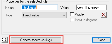
All these general variables always start with gen_ (gen comes of general = commonly used).
If you do not add this gen_ prefix to the name, then Parabuild will automatically add the gen_ prefix.
Groups
First of all you must enter a short and a long name for the macro.
Example Short: Haunch Long: Haunch with end plates, reinforcements and stiffeners
These two names are used in the Review macro dialog box when several macros are selected: it allows editing these macros simultaneously (those with the same short name).
Lower in the dialog you can enter a group name for each module that exists in the macro.
Each module will automatically receive a tab in the Review macro dialog box.
But in case you have many modules and you want fewer tabs (many modules is the best manner of working) then you should give the modules that must be merged a common group name.
For example two stiffeners that were each placed in another module: “Stiffener-left” and “Stiffener-right”.
You can give both modules the group name “Stiffeners” and the variables of both modules will be merged in one tab called “Stiffeners”.
When tabs are merged, the variable names are also merged :
In case they have the same name they will be merged into one variable. When the user modifies this variable then that modification will be made for both dimensions in both modules.
Sorting number: Using this number you can determine the order in which the modules appear in the Review macro dialog box.