DSTV NC Settings
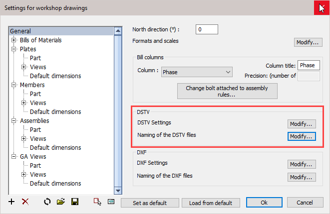
Settings for DSTV files may be changed from the Document generation Settings / General
Scope of these settings
This topic explains the general Dstv settings.
However the settings for weld contours and match lines are general settings that apply to all CNC files, not just the Dstv files.
You can read more about these general settings in these 2 topics :
- The Check CNC contours when numbering parts settings influence the numbering of parts, so that the CNC filenames become shorter and simpler.
- The CNC contour and matchline settings allow you to enable lines or punch marks in the CNC files automatically at the locations where parts need to be welded. This will greatly reduce time spent and mistakes made in the workshop.
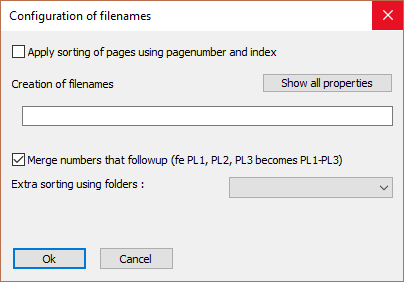
Naming of Dstv files
Clicking the DSTV Settings / Naming of the DSTV files button will open the following dialog where you can change the following settings :
Clicking the DXF Settings / Modify button will open the following dialog where you can change the following settings :
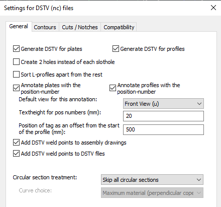
General tab
The options in the dialog box are explored below.
Generate DSTV for plates - When activated, DSTV files will be generated for plates.
Generate DSTV for profiles - When activated, DSTV files will be generated for profiles.
Create 2 holes instead of each SlotHole - If activated then Parabuild will insert two holes in the DSTV file instead of a single slothole. This is useful if the machine doesn't have a tool for creating slotholes.
Sort L-profiles apart from the rest - If activated then the DSTV files of L-profiles will be stored into a separate folder. This is useful when the L-profiles need to be done with a different machine.
Annotate plates with the position number - The machine that supports this will engrave/write the position number on the plate.
Annotate profiles with the position number - The machine that supports this will engrave/write the position number on the profile.
Default view for this annotation - Here, you can choose on which side of the part the position number should be scribed.
Text height for position numbers - Set the text height for position numbers scribed on the part.
Position of tag as an offset from the start of the profile (mm) - This setting only applies to the tag of the part itself (not the tags of parts that are welded to it). The tag is positioned at the beginning of the part, plus this offset value. This value is always in millimeters, regardless of the drawing's units
Add DSTV weld points to assembly drawings - For each weld point in DSTV Parabuild well draw a cross in the assembly drawing.
Add DSTV weld points to DSTV file - The drill of the machine can be used to create a dot to facilitate the welder. You can find out more about this in the DSTV weld points topic.
Circular section treatment - Select a treatment option for Circular hollow sections or circular bars.
- Skip all circular sections - No Dstv files will be generated for CHS profiles or round bars.
- Process end-cuts only - The circular profiles will be treated like any other profile. Due to the circular form, no holes can be described in the dstv file if this option is enabled. And only simple planar end-cuts will be described in the dstv file.
- Process with wrap-around method - A wrap-around of the circular profile will be written in the Dstv file. This method writes a detailed description of the holes and cuts of the section in the Dstv file. Use the Curve choice option to configure the wrap-around calculation method.
Curve choice - In case of the wrap-around method, choose how the curves of the wrap-around should be calculated.
Generating the wraparound of the 3D model will cause a loss of information.
We are after all exporting just 1 layer of the pipe, whereas the actual pipe in 3D consists of many layers that could be exported.
These are the available options for the curve choice :
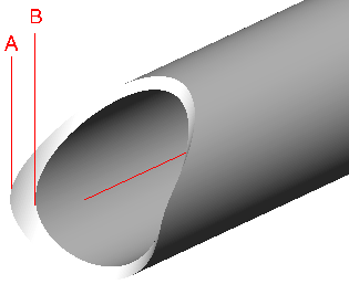
- Inner cylinder - The curves of the inner cylinder are used (cylinder B in the illustration)
- Outer cylinder - The curves of the outer cylinder are used (cylinder A in the illustration)
- Minimum material - Parabuild will choose the inner or outer automatically depending on which would cut the most amount of material away. Perpendicular cutting is assumed.
- Maximum material - Parabuild will choose the inner or outer automatically depending on which would cut the least amount of material away. Perpendicular cutting is assumed.
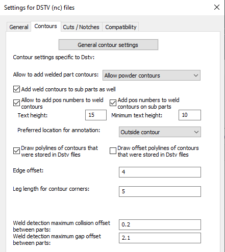
Contours and Match lines
General contour settings - Many of the contour and match line settings are stored generally, because they apply to both Dxf and Dstv files. Also the numbering can optionally be influenced by the contours and match lines. See the CNC contour and match line settings topic for more information.
Also related to the contours and match lines are the Check CNC contours when numbering parts settings.
Allow to add welded part contours - This setting works as an override of the general contour settings. By disabling the contours here, the general contour settings are ignored. Here you may choose between either, Punch / Powder / or Both. If you choose 'Both' then all the contours are added double to the DSTV file.
Add weld contours to sub parts as well - When you enable this, then weld contours will also be added to sub parts that are touching other sub parts. This will occur in assemblies where 2 sub parts are touching each other.
If this option is disabled, then only the subparts that are touching the main part will get a contour on the main part.
Allow to add position numbers to contours - This setting works as an override of the general contour settings. By disabling the position numbers here, the position numbers are not added, regardless of what the general contour setting is set to. When you enable this, then weld contours that are placed on a main part will get a position number text close to them.
Add position numbers to weld contours on sub parts - When you enable this, then weld contours that are placed on sub parts will also get a position number text. This will occur in assemblies where 2 sub parts are touching each other.
Text Height and Minimum text height : Here you may select the text height and minimum text height. If the part number text is located (especially) inside the contour, then a reduced height may be used. With this option, you can choose the minimum text height that the function is allowed to use for this purpose.
The Preferred location of the annotation - The default behavior is to place the annotation outside of the contour. If you choose to place it inside the contour, but the text is too large, then Parabuild will automatically place it outside anyway.
Selecting 'No Preference' will allow Parabuild to select the most suitable position.
Draw PolyLines of contours that were stored in the DSTV files - When this is enabled, Parabuild will draw a contour in the 3D model for each contour that it has written in the Dstv file. This is useful for checking the contour results, but this can clog your 3D model with lines.
Draw offset polylines of contours that were stored in Dstv files - Same as above, but a larger offset around the contour will be drawn
Edge offset - Parabuild will trim the contour so that it does not come any closer to any edges than this offset value.
Leg length for contour corners : The length of each leg of the contour corners
Weld detection, maximum collision offset between parts - If the welded parts collide with each other too much then the weld contour won't be added to the DSTV file.
Weld detection, maximum gap offset between parts - If the gap between the welded parts is too much then the weld contour won't be added to the DSTV file.
Cuts / Notches
These options allow you to automatically :
- Add chamfers to cuts/notches
- Add fillet arcs to cuts/notches
- Add corner arcs to cuts/notches
- Swap fillet arcs for corner arcs
- Swap corners for drill holes
- Swap arcs for drill holes
This will allow you to match the Dstv files generated by Parabuild with the machine's capability.
These options will also require less modeling in 3D, as arcs can simply be skipped because they can be added by the Dstv export automatically.
The following options drive these capabilities :
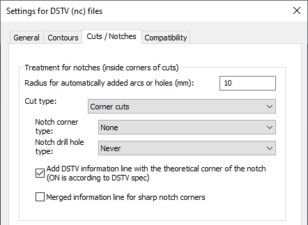
Treatment for notches (inside corners of cuts) - When enabled, Parabuild will automatically add holes and/or arcs to notches. Notches will be detected automatically in the cuts of the 3D models. Arcs/holes are added to the DSTV file only, the actual 3D model is not modified. Therefore there is no update of the part numbers when arcs or holes are automatically added by these settings. By using this option the user could choose to omit 3D modeling these arcs/holes, saving valuable time.
Radius for automatically added arcs or holes - The radius for any arcs or holes that are added automatically. Warning! This value will always be in millimeters, even when you are working with imperial units.
Cut type - There are three distinct types of cuts that have notch settings. For each of these three types there are settings to modify below after selecting the cut type.
Make sure to review the settings for each of these cut types :
- Corner cuts - Cuts that cut away a corner at the end of the profile (AK block in DSTV)
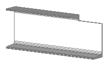
Example of a corner cut
- Outer cuts (all but corners) - Cuts at an edge of the member's material, except corner cuts (AK block in DSTV)
Example of an outer cut
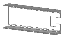
- Inner cuts - Cuts that do not reach the edge of the material, forming a hole in the material (IK block in DSTV)
Example of an inner cut
Notch corner type - The type of arc that should be inserted at notch locations that do not have an arc yet:
- None - No arc is added and no hole is drilled at the corner
- Fillet arc - A basic fillet is added to the corner (arc with angle < 180°)
- Corner arc - An arc with its center at the corner of the cut (arc with angle > 180°)
- Corner hole only - No arc is added, only a drill hole is created centered at the corner of the cut
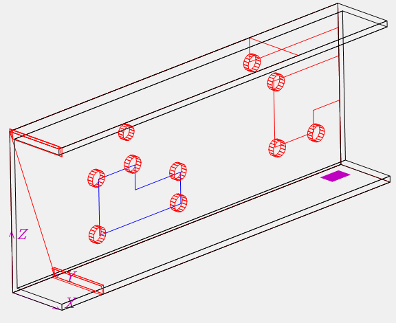
Consider the following Dstv end-results that are generated automatically from the same 3D model:
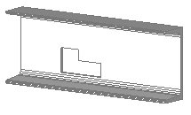
This is the example 3D model that incorporates the 3 different cut types. This is the original unmodified model thus generated with the notch corner type None
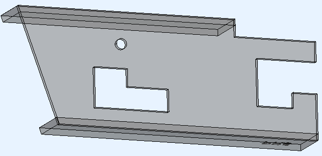
The example 3D model generated with the notch corner type Fillet arc enabled

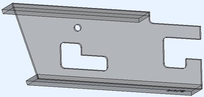
The example 3D model generated with the notch corner type Corner arc enabled
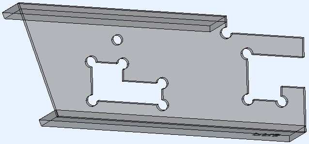
The example 3D model generated with the notch corner type Corner hole only enabled.
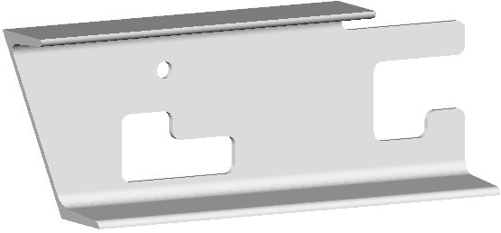
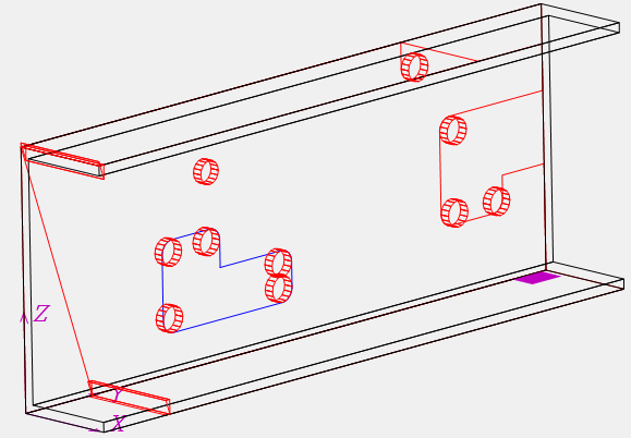
In some Dstv viewers we can't see the difference between the arc and the hole because the end-result is the same.
The second image shows a view with a different representation for holes compared to arcs.
Notch drill hole type - This option will cause drill holes to be placed on top of fillets and/or corner arcs. This is done both for 3D modeled arcs and for those automatically added using the "Notch corner type" setting.
This option can be used in the following scenarios:
- The machine can't cutout the current cut type. By adding holes to the cut corners, the machine will drill a hole for each inside corner. This in turn reduces the amount of manual labor still needed to cut out the remainder material manually.
- The machine can do the cut-out, but it takes too much time. Only drilling the holes for each inside corner of the cuts will reduce the time needed per cut.
- When a cut is removed, this can result in excess material falling off the part when the last part of the cut is done. Care should be taken that this material does not fall on the moving drill/mill. Depending on the machine's programming for this situation, the machine operator may want to deal with this problem himself/herself. A way to avoid this issue entirely is to not cut out the material but to use this option to only add holes in the cut's corners.
Do note that this option will add holes on top of the corners of the cut, but the cut themselves will still be added to the Dstv file.
The machine operator will still have to instruct the machine to not process the cut if you want to use this option in the above scenarios 2 and 3.
In scenario 1, we are assuming that the machine will automatically warn that the cut can't be processed by the machine.
The following drill hole options are available :
- Never - Drill holes are not automatically added
- For fillet arcs - A drill hole is added only on top of fillet arcs
- For corner arcs - A drill hole is added only on top of corner arcs
- Fillet and corner arcs - A drill hole is added on top of both fillet and corner arcs
Consider this example 3D model :
This is the model as it is drawn in Parabuild
This is the end-result after generating the Dstv with the option Drill hole type For fillet arcs enabled.
Extra holes are added on top of the existing arcs.
Add DSTV information line with the theoretical corner of the notch (ON is according to DSTV spec) -
For inside corners, this activates the additional information line with the point at the theoretical intersection of the notch edges.
The DSTV specification contains this line, but it is not suitable for all machines.
Merged information line for sharp notch corners - Only for sharp corners of notches; instead of a separate notch information line the 't' or 'w' tag gets merged into the regular line of the corner point
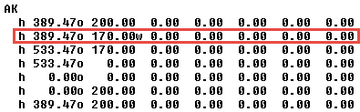
An example of a sharp corner model's Dstv file with the merged line option enabled
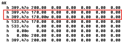
The same example of a sharp corner model's Dstv file with the merged line option disabled
Compatibility settings
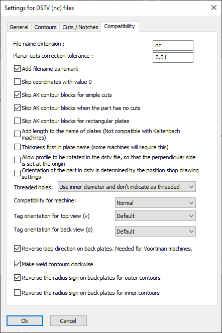
Some machines do not follow the DSTV standard, or are based on an old version of the DSTV standard. That is why some compatibility settings are necessary in order to support as many machines as possible. Only change these settings if you are experiencing problems with reading the DSTV files in your CNC machine.
Add filename as remark - Some machines expect this, and it does no harm.
Planar cuts correction tolerance - This settings filters out small planar cuts using a tolerance. Thanks to this option, the machine will not block on double saw cuts on one end of the profile if one of the cuts is negligible.
Skip coordinates with value 0 - Some machines do not expect any values with value 0 in the DSTV file.
Skip AK contour blocks for simple cuts - Some machines always need the AK block, others don't support the AK block at all.
Skip AK contour blocks when the part has no cuts - See above
Skip AK contour blocks for rectangular plates - See above
Add length to the name of plates - Normally the plates receive a name such as PL150x10. But some machines also expect the length in this name, so it will become PL150x10*200.
Thickness first in plate name - Some machines will require this
Allow profile to be rotated in the DSTV file so that the perpendicular side is set at the origin
Orientation of the part in DSTV is determined by the position shop drawing settings
Reverse loop direction on back plates - This is needed for Voortman machines
Make weld contours clockwise
Threaded holes
Compatibility for machine - These are a collection of changes to the standard that some old machines need