DXF Settings
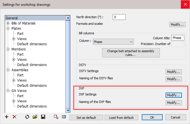
Settings for DXF files may be changed from the Document generation Settings / General
Scope of these settings
This topic explains the general Dxf settings.
However the settings for weld contours and match lines are general settings that apply to all CNC files, not just the Dxf files.
You can read more about these general settings in these 2 topics :
- The Check CNC contours when numbering parts settings influence the numbering of parts, so that the CNC filenames become shorter and simpler.
- The CNC contour and matchline settings allow you to enable lines or punch marks in the CNC files automatically at the locations where parts need to be welded. This will greatly reduce time spent and mistakes made in the workshop.
Clicking the DXF Settings / Modify button will open the following dialog where you can change the following settings :
The General tab
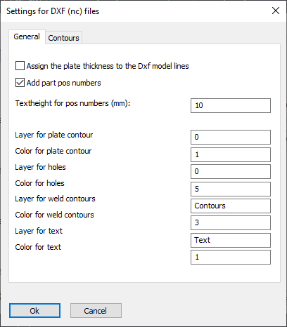
Assign the plate thickness to the Dxf model lines - When active, the thickness of the plate will be assigned to the model lines in the dxf files. This creates a semi 3D model and the machine can know the required thickness of the plate this way. Some machines can't read the dxf file when this option is active.
Add part position numbers - The position number of the plate will be added as text to the DXF file so that the machine can engrave it on the plate.
Text height for position numbers - Set the text height for position numbers on the part.
* The remaining options allow you to set the layers and colors of the different line types and texts.
The contours tab has the following options :
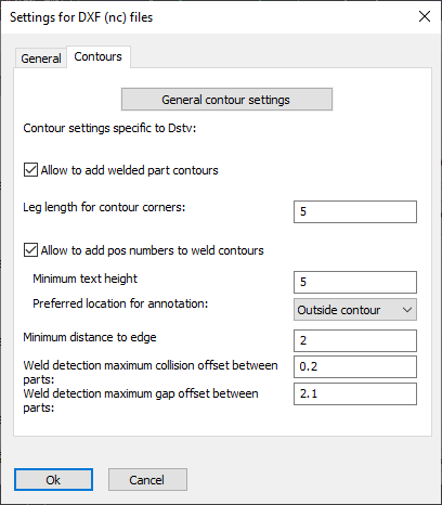
General contour settings - For more information about the options behind this button, see the CNC contour and matchline settings topic.
Also related to the contours and match lines are the Check CNC contours when numbering parts settings.
Allow to add welded part contours - When active, the weld contour options become visible. Contours will be added as per the CNC contour settings.
Leg length for contour corners - This is the length of the 2 legs whenever a contour corner is drawn
Allow to add position numbers to weld contours - Wen active, position numbers will be added to weld contours as per the CNC contour settings.
Minimum text height - Set the minimum text height for the position numbers of the contour. Parabuild will deviate from the standard text height in order to fit the text in places without much room, but will not use a text height below this value.
Preferred location for annotation : Normal behavior is to place this annotation outside of the contour. You can choose inside of the contour, but if the text is too large to fit in the contour then it will be placed outside of the contour.
Minimum distance to edge - Set the minimum distance that should be kept between the text and the edge of the plate
Weld detection, maximum collision offset between parts - If the welded parts in 3D collide with each other too much then the weld contour won't be added to the DSTV file.
Weld detection, maximum gap offset between parts - If the gap between the welded parts in 3D is too much then the weld contour won't be added to the DSTV file.
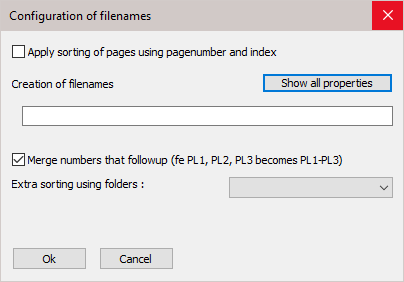
The Naming of the DXF files button will open the following dialog where you can change the following settings :