Annotation styles and groups
Command - Prb_TagSettings
Activating this command will open the Annotation styles and groups dialog, which can also be accessed from the Sheet Properties dialog.
---------
 Annotations styles and Annotation groups are now split.
Annotations no longer need to be part of a group in order to be used when drawing an annotation, and multiple groups can refer to the same annotation.
This makes annotation styles much easier to configure.
Note that only groups have filtering features for letting Parabuild automatically choose a style based on filtering rules.
In many locations throughout the Parabuild settings there are dropdown boxes for choosing an annotation style or group to be used.
Here both the groups and the individual styles will show up in the same dropdown, grouped together by type.
All the default Parabuild style names that come with a fresh installation of Parabuild now start with "Pb ", to differentiate them from user styles.
Note that the annotation styles and groups that start with "Pb " may be overwritten when an update of Parabuild is installed.
The annotation styles and groups are stored in this folder for Metric drawings : \Pb_Lib\Dialog Templates\Tag Defaults\Metric\
And in this folder for Imperial drawings : \Pb_Lib\Dialog Templates\Tag Defaults\Imperial\
In older versions, namely version 7 and all older, the styles were stored in this folder : \Pb_Lib\Dialog Templates\Tag Defaults\
The styles of these older versions could be copied to the Metric or Imperial folder, but the styles will then need to be checked because the filtering capabilities of the old styles will be lost.
Annotation groups
Annotation groups are used to let Parabuild draw different annotations based on filters.
For example when a hole is selected we may want a completely different annotation than when a part is selected.
The annotation groups have the following capabilities :
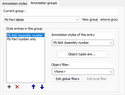
Style entries in this group - This list contains all of the different styles that this group supports. The minimum is 1. Use the up and down button to change the order of the items in the list. The order of the items does matter because the first item in the list that positively matches filter values will be used to draw the annotation.
Annotation style of this entry - Choose the annotation style that is to be associated with this entry
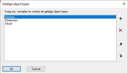
Object types are - Choose one or several object types that are required for this annotation entry to be used. Object types can also be holes or assemblies.
Object filter - Choose the optional object filter that is required for this annotation entry to be used. This is a filter in addition to the above object types.
Annotation styles
Annotation styles simply store all the properties that the new annotations should receive.
Highlighted here are the new properties in this version:
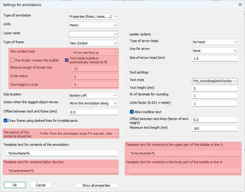
The annotation style has the following new properties :
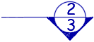
- View symbol type - Whenever the frame type View Symbol was activated this option will become available allowing us to choose the view symbol with an arrow in any of the 4 directions. An example view symbol with arrow down is :
If the option without arrow is drawn then the symbol looks like this :
- The divider crosses the bubble - This option enabled looks like this :

This option disabled looks like this : - Text inside bubble is automatically resized to fit - When this is enabled, the size of the text inside the bubble will be decreased to fit the text inside the circle.
- Minimum length of divider line - Use this to increase the divider line's length in case no text is shown on the line such as with this example :
- Circle radius - Choose the radius of the bubble here (paper units)
- Text height in circle - Choose the default text height of the text inside the bubble here (paper units)
- The source of the contents should be - When there is an annotation template in both the shop drawing settings AND the annotation style, you can now configure which gets preference
- Template text for contents of the annotation - This is the normal text that any annotation has. In the case a divider line was enabled this will be the text above the divider line
- Template text contents for contents below the line - In the case a divider line was enabled this will be the text below the divider line
- Template text contents for contents in the upper part of the bubble or line 3 - When a bubble is activated this will be the contents of the text in the upper part of the bubble
- Template text contents for contents in the lower part of the bubble or line 4 - When a bubble is activated this will be the contents of the text in the lower part of the bubble
----------
This dialog allows you to create and modify annotation styles. Each annotation style is part of an annotation group.
The purpose of the annotation group is to allow us to access multiple styles from a single icon.
If we take for example the Position number group, which is accessed through this icon  : we can use this icon to draw a part number tag or a bolt tag, both of which have a completely different annotation style.
This is accomplished by adding multiple annotation styles in the group, and also by correctly setting the Object types per style (explained below).
The group name can be used directly on the command line to draw annotations using the command name as follows :
(Prb_TagGroup "Group name")
By using the above line as the command line command in a new icon, it is possible to create custom icons that access custom annotation styles.
Alternatively, we can also access custom group names from the Other Annotations command in Parabuild. Creating a new icon is not necessary thanks to this command.
The actions in this dialog are explored below :
Current group and New group - These allow you to manage the groups
New style - This will create a new style within the current group
Remove style - This will remove the selected style
Edit Style - This will open the Settings for annotations dialog
Change object types - This allows us to change the object types for the currently selected style.
As explained above, the object types in this list allow us to dictate which style should be used for each different object type.
Settings for property annotations
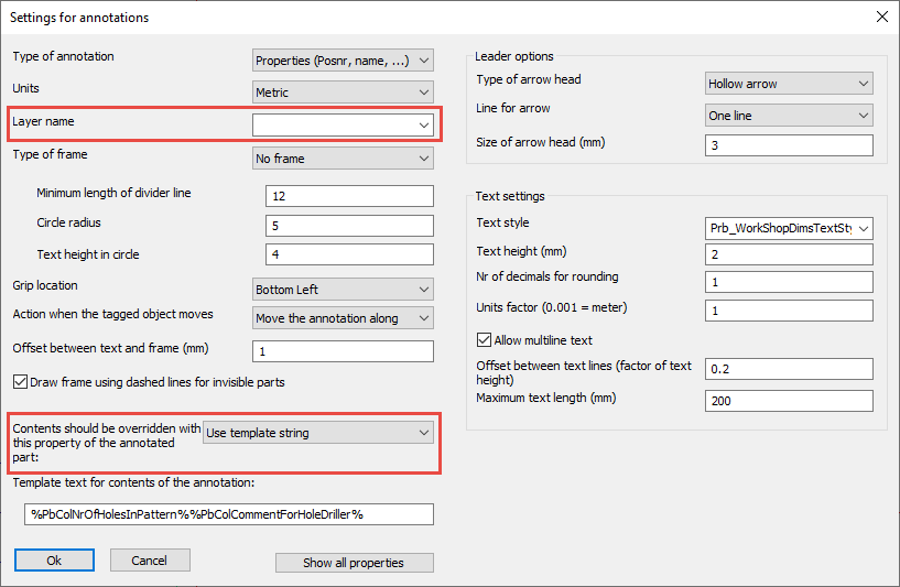
Many of the options in this dialog box are self-explanatory, but we will explore the less obvious options :
Type of annotation - The following annotation styles are available :
- Properties - This is the typical annotation that displays one or more properties of a 3D part
- Comment - This annotation type's purpose is to show a manually written comment. In essence there is no difference with the properties type.
- Property through proxy object - This annotation type is the same as the Properties type. But a difference was created here to allow the user to differentiate between an annotation that shows the property of a part directly, or 'by proxy' when the annotation is touching the part indirectly.
An example could be an annotation touching a dimension. Usually, the annotation would not depict properties of the dimension but rather properties of the part that is dimensioned. - Arrow for section view - This type has some unique properties that only apply to section annotations. A section annotation is used to depict the viewing direction and location of a section view. For more about the options, see below.
- Level annotation - This type has some unique properties that only apply to level annotations. For more about these options, see below.
Units - Choose between metric and inches here. This is used by Parabuild to filter out metric styles in an inches model, and filter out inches styles in a metric model.
Layer name - It is now possible to specify a layer name for newly created annotations in the annotation style. When it is empty, the annotation will be set to the layers Pb_TracWorkshopTags or Pb_TracGATags, depending on the command that draws the annotation.
Type of frame - All of the frame types should be obvious except for Text above and below a divider line.
This frame is an annotation with 2 or 3 text fields. For more information about this, see the Minimum length of divider line and Circle radius options.
- Minimum length of divider line - This option will only work if the text %HorDivider% is used in the Template text (see below). The purpose of this is to draw an annotation with a horizontal divider that has text above and below the divider line. The contents before the %HorDivider% will be displayed above the divider line, the text after the %HorDivider% will be drawn below the divider line
- Circle radius - This option will only work if the text %BubbleText% is used in the Template text (see below). The text that is written after the %BubbleText% will be drawn inside a circle. The circle will be drawn on the left-hand side of the divider line.
- Text height in circle - This is the height of the text inside the special %BubbleText% circle.
Grip location - This is the location where the cursor attaches to the frame when we try to move an annotation frame.
Action when the tagged object moves - What Parabuild should do when the tagged part moves. Not implemented yet.
Offset between text and frame - Choose the offset between text and frame which will only have an effect when the frame is drawn
Draw frame using dashed lines for invisible parts - Not implemented yet.
Contents should be overridden with this property of the annotated part - This override property is adjustable in the annotation style for annotations that will be created, and also in the properties panel of existing annotations.
This override has the following options :
- Use template string - This is the default setting, and it effectively disables the override : The normal Template text is used for the contents of the annotation.
- Use label template 1 or 2, otherwise template string - When one of these is chosen, the annotation will retrieve the label template property from the annotated part. The label template property can be adjustable in the Properties panel of profiles, plates, structures and volumes.
When the label template is empty, the regular template text of the annotation is used (which effectively disables the override).
This option allows you to make the annotation's contents specific to the part that is annotated.
It is possible to set this label template automatically using structural types, which allows you to then automate the contents assignments of the annotations. This is more thoroughly explained with an example in the Label templates topic.
Template text for contents of annotation - This is the most important option for the annotations.
With this option we can decide the contents that should be written in the annotation.
We need to use variable names to set the properties that should be depicted in the annotation.
But it is still allowed to write regular 'static' text in the same string.
The variables are always entered between % symbols to make this possible.
Some examples annotation texts that demonstrates this mix :
The template text for a hole annotation :
ø%PbColBoltDiamater%
Could result in the text :
ø16
The template text for a profile annotation :
%PbColPosNumber%-%PbColName% L%PbColLength%
Could result in the text :
PR1-IPE200 L3590
Use the button Show all properties to display all the Part properties that Parabuild supports.
Type of arrow head -
Line for arrow - At the time of writing, only the options None and One flexible line and a fixed line are supported.
Size of arrow head -
Text style -
Text height -
Number of decimals for rounding -
Units factor -
Allow multi-line text - When enabled, the text will be shown on multiple lines if necessary. The below options will decide when new lines are introduced :
Offset between text lines - This is measured as a factor of the text height
Maximum text length - If the text field would become larger than this value, then a new line will be introduced.
Settings for section annotations
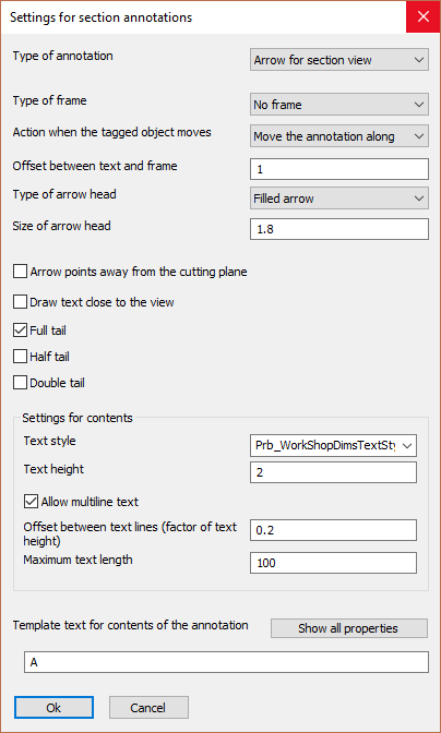
Many of the options in this dialog box are the same as the regular annotations dialog box, except these:
Arrow points away from the cutting plane - This determines the position of the text relative to the cutting plane.
Draw text close to the view - This determines the position of the text relative to the view.
Full tail : 
Half tail : 
Double tail -
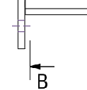
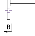
The above 5 options allow us to draw the section annotation in either ISO or ASME style :
|
|
|
|
ISO style |
ASME style |
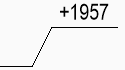
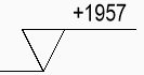
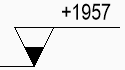
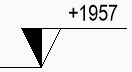
Settings for level annotations
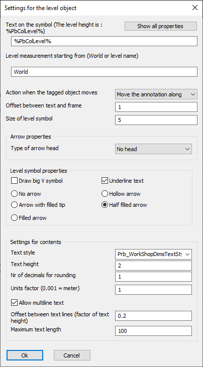
Many of the options in this dialog box are the same as the regular annotations dialog box, except these:
Text on the symbol - This works the same as the Template text of the property annotations. The only difference is that for this annotation type the variable %PbColLevel% can be used.
Level measurement starting from - This should be "World", or the name of the level that should be used as starting plane for the height measurement. Levels can be reviewed in the Modify levels topic.
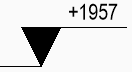
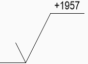
Draw big V symbol :
|
|
|
|
An example level annotation with Draw big V symbol enabled |
An example level annotation with Draw big V symbol disabled |
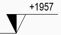
Underline Text :
|
|
|
|
An example level annotation with Underline text enabled |
An example level annotation with Underline text disabled |
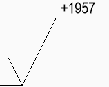
Tip type or arrow type :
|
|
|
|
Tip set to : None |
Tip set to : Hollow |
|
|
|
|
Tip set to : Filled tip |
Tip set to : Half filled |
|
|
|
|
Tip set to : Fully filled |
|