Sheet properties
This dialog may be opened in one of two ways:
- By Right clicking on a 2D sheet in the Sheets manager. This will enables you to edit the properties of the currently active sheet, editing these properties will only work with the currently active sheet.
- It can also be opened by clicking on Settings in the Sheets manager and in that dialog clicking on the Drawings tab, and under that the sub tab called Sheets :

Editing the settings by this route will effectively establish them as a default for all future sheets of this type.
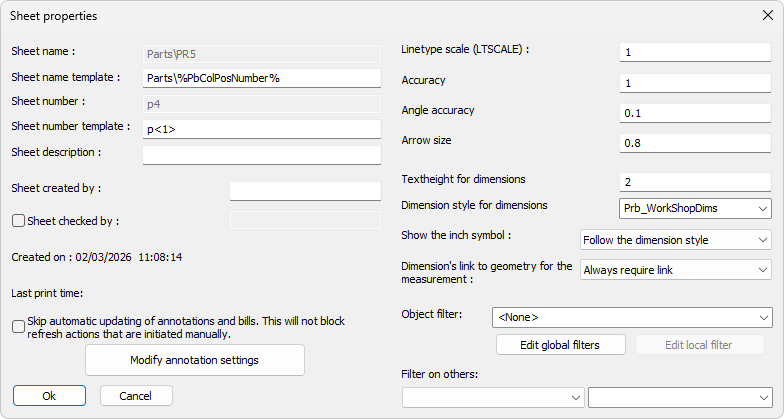
In this dialog box you can change the following settings :
Sheet name -
Sheet name template -
Sheet number - By default, the sheet number is the same as the sheet name, here, you may change the number manually
Sheet number template -
Sheet created by - This field can be user for tracking purposes
Sheet checked by - Not yet implemented
Created on - The created time and date are recorded automatically
(The properties Sheet number, Sheet created by and Created on properties are written to KISS files - See Export BIM to File for more information on KISS file settings)
Last print time - This field will contain the last date and time that this sheet was printed
Skip automatic updating of annotations and bills - When this is enabled, Parabuild will not attempt to update the annotations nor bills on this sheet. This automatic updating process will happen most often with annotations when the sheet is opened, when the sheet is printed or exported, and even when a 3D camera that is used by one of the views on the sheet changes.
Keep in mind that manually refreshing this sheet will still update the annotations and bills, so we can't call this setting a "sheet lock".
Modify annotation settings - This is explained lower in this topic
Line type scale - The scaling of dashed lines and center lines
Accuracy - The measurement accuracy for linear dimensions
Angle accuracy - The measurement accuracy for angle dimensions
Arrow size - The size of the arrows of dimensions.
Text height for dimensions - The text height of all dimensions on the sheet
Dimension style for dimensions - The dimension style (AutoCAD) for all dimensions on the sheet
Show the inch symbol - This allows us to remove the inch symbol in specified cases.
With this setting we can have the inch symbol removed from part/assembly sheets, while using the same dimension style on GA drawings, where you might want to keep the inch symbol. 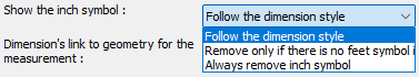
Dimension's link to geometry for the measurement - This settings was added to let the user take control when unlinked dimensions become red and getting brackets :
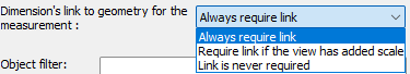
When this is set to Link is never required then the link between the 2D view and the 3D model is not required by Parabuild, meaning the dimensions's measurement is left as-is.
The measurement is done on the 2D view whether the lines and scaling are correct or not and it becomes drafter responsibility to make sure the value is correct.
The default value is off (Always require link) because unlinked dimensions are risky. But it is less risky if you do not use added scale and no shortening.
The dimension value can be wrong when :
- The view has an added scale (added scale compared to the sheet scale)
- The view is shortened
It is recommended to disable shortened views when you use this option.
It is very easy to create faulty dimension values with shortened views in combination with entities on 2D paper space like shown in this example : 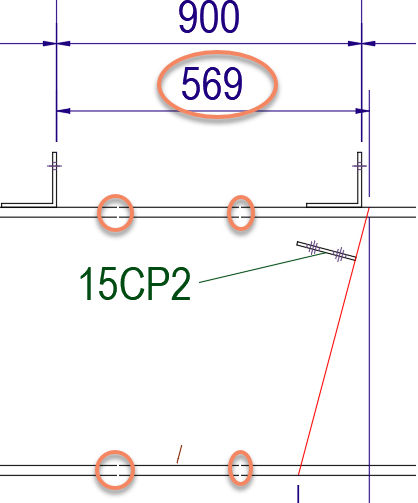
Warning Here is an example where the measurement 569 is wrong because dimension linking was disabled, and shortening was enabled on the view, and the freely drawn red line was used to measure to
Object filter - You can use this to use the Advanced object filter on all the views on this sheet.
This is an aggressive filter because it will filter objects from all the views, existing and new views.
The changes done to this property will be reflected when the sheet is refreshed.
Filters on others - You can use this to filter all the views on this sheet with one of the simple property filters.
This is an aggressive filter because it will filter objects from all the views, existing and new views.
The changes done to this property will be reflected when the sheet is refreshed.
Show all properties
With this button you can review all variables that can be used in the text template of annotations.
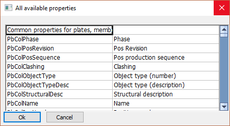
More information about all of the properties that can be used in text template can be found in the Properties to be used in annotations and bills topic.
When you click on the button you can change the following annotation settings that apply to the sheet :
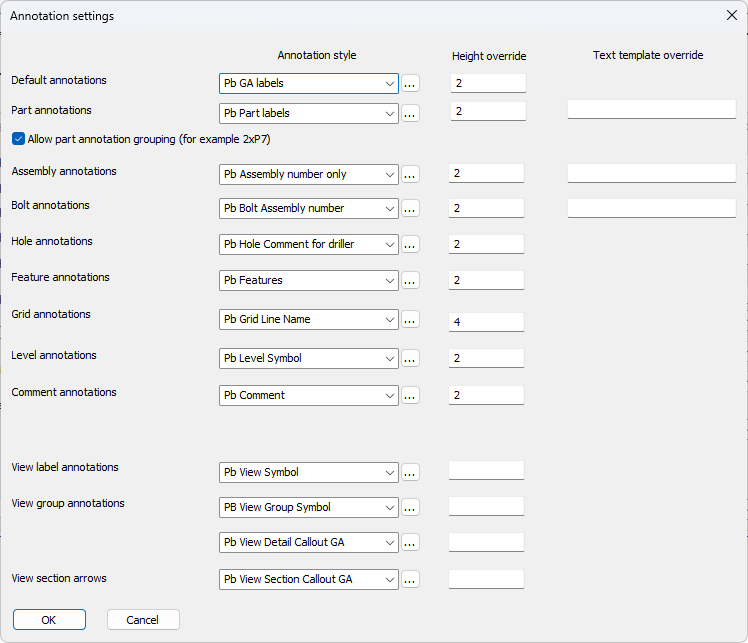
Non applicable settings will be enabled or disabled for certain sheet types. This is shown in the descriptions below.
Default annotations -
Part annotations -
Allow part annotation grouping -
Text height for level - The text height for all level annotations on the sheet
Style for level - The text style for all level annotations on the sheet
Text height for comment - The text height for all comment annotations on the sheet
Style for comment - The text style for all comment annotations on the sheet
Text height for assembly annotations - The text height of all assembly number annotations on the sheet. (Not applicable for Plates and Members)
Text style for assembly annotations - The text style of all assembly number annotations on the sheet. (Not applicable for Plates and Members)
Text template for assemblies - This is a text override for assembly number annotations. Enter the text that should be shown in the frame of the annotation. Use variables that can be entered between % symbols. Look at all the available variable names by clicking the button Show all properties button at the bottom of the dialog.
If you leave this value empty then the override is not in effect and the text of the annotation style will be used.
Style for others: View name, Position number, Grid, Bolt, Hole - The style for all other annotations such as members, holes, bolts, etc...
Text height for hole/bolt/part annotations - The text height for annotations on holes and bolts.
Text height for position number annotations - The text height for position number annotations.
Text template for positions - This is a text override for position number annotations. Enter the text that should be shown in the frame of the annotation. Use variables that can be entered between % symbols. Look at all the available variable names by clicking the button Show all properties button at the bottom of the dialog.
If you leave this value empty then the override is not in effect and the text of the annotation style will be used.
Text template for bend lines - This is the text that will be used on all annotations for the bend lines on the unfolded views.
The following properties can be used in this text template :
- PbBillColUnfoldedName
This will contain the name of the unfolded plate when the part was already unfolded.
The name includes the thickness, width and length of the unfolded plate. - PbBendRadius
This will contain the bend radius of a bend line of an unfolded part.
This will only work in annotations when the annotation arrow points towards a bend-line of an unfolded part on shop drawings. - PbBendAnglePlusMinus
This will contain the bend angle of a bend line of an unfolded part.
The angle is in degrees and when it is positive, then the bend should be done in the +Z direction of the view.
This will only work in annotations when the annotation arrow points towards a bend-line of an unfolded part on shop drawings. - PbBendAngleUpDown
This will contain the bend angle of a bend line of an unfolded part.
The angle is in degrees and will add the suffix Up or Down to indicate the bending direction.
This will only work in annotations when the annotation arrow points towards a bend-line of an unfolded part on shop drawings.
Text height for section annotations - The text height of the annotation of end plate views and section views on assembly workshop drawings. (Not applicable for Plates, Members and GA views)
Text style for section annotations - The text style of the annotation of the end plate views and section views on assembly workshop drawings. (Not applicable for GA views)
Text height for view number annotations - The text height of view numbers 1,2,3,4 that are shown on workshop drawings. (Not applicable for GA views)
Text style for view number annotations - The text style of view numbers 1,2,3,4 that are shown on workshop drawings. (Not applicable for GA views)
Text height for grid annotations - The text height for the grid balloon text.
Text height for view annotations - The text height will generally be larger than other annotations.
Text template for main views - This is a text override for main GA view annotations. Enter the text that should be shown in the frame of the annotation. Use variables that can be entered between % symbols. Look at all the available variable names by clicking the button Show all properties button at the bottom of the dialog.
If you leave this value empty then the override is not in effect and the text of the annotation style will be used.
Text template for detail view - This is a text override for detail view annotations. Enter the text that should be shown in the frame of the annotation. Use variables that can be entered between % symbols. Look at all the available variable names by clicking the button Show all properties button at the bottom of the dialog.
If you leave this value empty then the override is not in effect and the text of the annotation style will be used.
Empty values in the fields
The text height and text template settings of this dialog box can be empty. If for example the text height of an annotations is empty, then the text height in the annotation style will be used instead.
Also if the text template of an annotations is empty then the text template in the annotation style will be used. The reason why these settings still exist here is so that we can still choose different text heights on a per-sheet basis and essentially override the settings chosen in the annotation styles.