Drawing settings
This topic explains the settings on the Drawings tab of the Document generation Settings dialog box.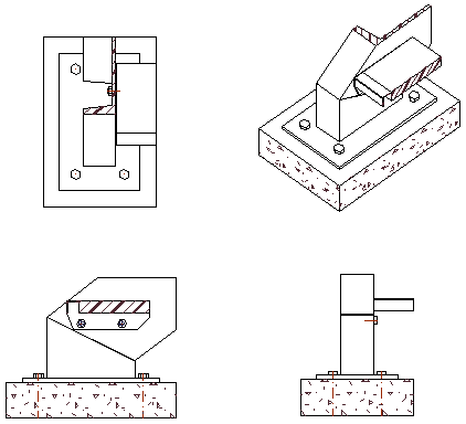
The drawings tab contains all of the settings for the shop drawings and GA drawings generation :

Each of these sub tabs are explained below.
1. Detail groups
This sub-tab is the primary location for the generation of part and assembly detail drawings (shop drawings).
The dialog is divided in 3 areas and each of those areas is explained hereafter.

Area A
On the left side Area A there is a list of detail groups.
These are all the settings that Parabuild will loop from top to bottom when a shop drawing for a part or assembly needs to be generated.
When a detail group is selected, the settings for that group will be shown on the right side (Area B and Area C).
The greyed-out groups in this list are not active so they will be ignored for the generation of sheets.
These disabled groups provide a quick way to influence the sheet generation if some of them are activated additionally. Review the names, filters and settings of the groups to learn about the purpose of each group.
Note that the order of the items in this list has a big influence on the result of the sheet generation.
Area B
At the top Area B there is a filtering/validity section for the selected group. These settings will determine whether or not this group will be used for a specific part or assembly.
If both the part type and the object filters match, then this group will be used for the part/assembly. The views of the part will be generated with the settings in this group and the generation process stops for this part or assembly.
In between Area B and Area C we have the following 2 options :
This group is active - When this group is deactivated then the entire group will do nothing and it will be ignored during sheet generation. Deactivation is primarily here so that the out-of-the-box settings can contain many common workshop practices and ideas that are inactive, but ready for you to try out simply by activating them.
This group is valid for xxx - When part drawings are added to assembly sheets, this pulldown can be used to configure different settings for parts on part sheets versus parts on assembly sheets. For example, when this option is set to "Assembly sheet", and "Disable shop drawings for all in this group" is turned on, then parts that match the filters of this group will have their part drawings added to the assembly sheets.
Area C
In Area C you can find the drawing settings of the selected group. These settings will determine everything there is to the generation of the views and the sheet.
It may look like there are not many settings but these settings actually refer to other collections of named settings.
This allows us to re-use configurations across multiple groups, and to easily switch between various named settings.
The 4 main collections of settings are View arrangements and appearance (2), Automatic dimensions (4), Sheet configuration (5) and Automatic generation of sheets (7).
All of these 4 have their own sub-tab at the top. By clicking on the other sub-tabs at the top you can review and modify all of the collections.
But you can directly navigate to the settings that are in use by clicking on the Modify button next to the dropdown box. This will directly open the correct sub-tab and the named settings collection within.
Then there are still sub-tabs 5, 6 and 7 which are not linked to directly by the detail group, but :
sub-tab 3 View appearance is referenced to by each view in the View arrangements (2)
sub-tab 6 Annotations is referenced to by Sheet configuration (5)
sub-tab 8 GA drawings stands on its own because it contains the settings for the creation of GA views.
The remaining options on the detail groups tab Area C are explained hereafter :
Disable shop drawings for all in this group - When this option is enabled no sheet will be generated for the parts or assemblies that match the filters of this group. Practical use cases for which this option could be useful are bought-in parts, off-the-shelf standard parts, and parts or assemblies that don't need to be processed by the shop.
Allow merging with other detail groups - This option allows parts of assemblies that are configured in different Detail groups to still end up on the same sheets. Merging of detail groups will only be applied when sheet settings, auto-generation settings and filenames are consistent.
When the assembly views are to be combined with single part production views, then Parabuild will search for a suitable detail group of each sub part individually.
Annotation template text for this group - This setting refers to the annotation underneath the group of views that will be generated for each part or assembly in this group. This "View group" annotation will be drawn below the main views and describes the part or assembly.
Folder name for exported sheets - This option does not relate to printing to PDF, it concerns exporting sheets to dwg files (each sheet exports to a .dwg file). Here you can specify an additional folder name under the 3D project location in which the exported dwg files will be stored in.
File naming - When opening this dialog the sub folder and name of the sheet can be changed.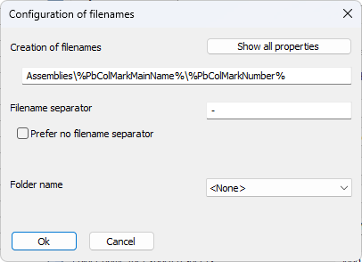
Creation of filenames - We can use the \ symbol to create folders. We can combine fixed text and any property between % symbols.
The folders and the name that are chosen here will be used for the sheet name in the sheets manager and when printing the sheet to PDF or exporting the sheet to a dwg file.
Adding properties like "thickness" or "section name" or "structural type" in the folder structure or sheet name is a good way to group similar parts together in the same folders and on the same gather sheets, if any.
Filename separator - This separator will be used when a sheet contains multiple part numbers or assembly numbers.
Folder name - This option will cause an extra folder to be created before the folders and filename that are defined in the Creation of filenames option above. This setting could be considered redundant but it offers a quick way to add a folder to the full path.
Allow multiple drawings for the same part/assembly if the filename differs - When the above folder and name contains properties such as %PbColPhase% then it may be possible that the parts/assemblies with the same number have a different value for that property (in this case different phase). Activate this option if you want Parabuild to create separate sheets if the property values in the name differ, even if they have the same part/assembly number.
Hereafter follows a more in-depth explanation of the other sub-tabs :
 2 View arrangements
In this View arrangements list the order of the items do not influence the sheet generation but they are sortable for the convenience of the user.
The General settings determines which part and assembly types view arrangement entry is intended. This will not be used as a filter for the sheet generation but it will be used by the dialog box to determine which detail groups and GA drawings can utilize these named settings.
The other options in the dialog box are explained hereafter :
Pre-configure view arrangement
These options are not available to arrangements for plates. The options under this button will automatically arrange the views for you.
Some of the options that are available here are :
- Switch between First Angle (EU) projection and Third-Angle projection (US)
- Choose the alignment of side views and ISO view to follow the 3D model or not
- Minimum and maximum number of side views
- Activate more front/back views
- Switch between following projection rules very strictly or move section and endplate views around to use the space on paper more smartly
Note that after clicking on Ok of the Pre-configure dialog box then the views of the current arrangement will be modified and re-arranged. Any manual changes that you did to them might be lost.
All the options in this dialog are explained in the Pre-configure View Arrangement topic.
Shortening and other settings
The available options in this dialog are explained in the View shortening and other options topic.
First angle projection - First angle orthographic projection is used often in the EU. Note that when you change this setting then the views in the list are modified and re-arranged, which may cause some of your manual changes to these views to be lost.
Third angle projection - Third angle orthographic projection is used widely in the USA. Note that when you change this setting then the views in the list are modified and re-arranged, which may cause some of your manual changes to these views to be lost.
The views list
On the left-hand side all of the views are listed. The first view should be the primary view, and other views may be optionally projected off the first view, or off any other view.
For isometric views and endplate views the ordering is not important, but for section views the first is the one that will be used when a section is manually added on the page.
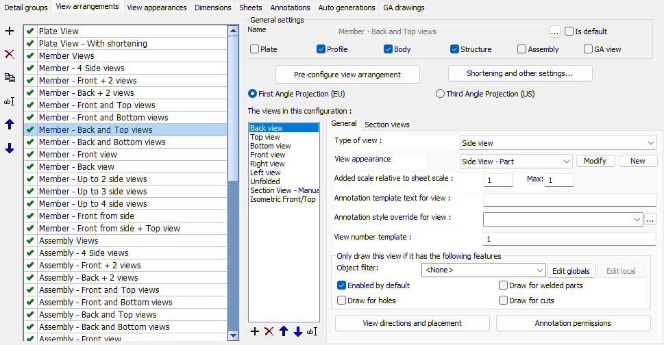
General

The available General options per view are :
Type of view - An important setting determining what kind of view this is : side view, endplate view, section view or Isometric view. This type allows Parabuild to determine appropriate behavior for this view.
View appearance - This refers to the appearance settings that need to be used for this view such as how to display holes, enable hidden lines or not, colors for lines and many more. Click on Modify to view and/or modify these view appearance settings.
Added scale relative to sheet scale - This can be used to increase the size of the view (for details) or to decrease it (Isometric views). There is a maximum scaling which is used for dimension-free isometric views during automatic sheet generation. Sheet generation will start out with the scale that you choose, and if there is more room on the page it will gradually enlarge the view up to the chosen maximum scale factor.
View number template - A template can contain a static prefix and suffix, and a start number between the symbols "<" and ">". For more information see the view numbering topic. For part or assembly side views this number will typically be a static number from 1 through 4, for section and endplate views a template <A> is used which means that Parabuild should start numbering alphabetically starting from A. For GA views the default is usually <1>, and views will get an increasing number assigned based on which views were already added to the current sheet.
View name override (optional) - If provided, the text entered here will be used in annotations that use the %ViewName% variable. If this value is empty then the view name as it is displayed in the view list will be used.
Annotation template text for view - Use this template text to add an annotation underneath that view for describing the view. This is by default used for endplate and section views in assemblies, or for GA views. A general annotation for the whole part or assembly can be set in the Detail groups tab.
Annotation style override for view - When the above template text is used then you can optionally choose an annotation style specifically for the above annotation. The purpose of this is to make the annotation stand out by making the text size larger or underlined, or for giving it a specific appearance such as a View Symbol.
Allow shortening - When this is enabled, the view will be shortened if shortened was activated. Having this option per view allows us to determine which views should be shortened and which ones shouldn't. Obviously side views should be shortened but the other views on the shop drawing shouldn't.
Only draw this view if it has the following features
Use the following options to automatically make the view be drawn or not, depending on what is visible in the view
- Object filter - This filter allow you to activate or deactivate each view based on any object filter.
- Enabled by default - When this is enabled the view will always be drawn no matter what the other filter options are set to
- Draw for holes - When this is enabled the view will be drawn when there are visible holes on it
- Draw for attached parts - When this is enabled the view will be drawn when there are attached part on it (in case of an assembly view)
- Draw for cuts - When this is enabled the view will be drawn when there are visible cuts on it
View direction and placement - Use these View direction settings to choose the viewing direction, the model placement on the page and the location of the view on the page for section views and endplate views
Annotation permissions - In this Annotation and dimension permissions dialog you can choose whether this view should be dimensioned, and what kind of annotations can be added on the view
Section views
These settings are only available to section views and they allow you to configure the automatic generation of section views on assembly sheets.
We can influence the following parameters :
- View direction and orientation
- View appearance including using object level overrides mentioned above
- Box size can be either absolute, or an offset relative to the objects in the section view
- Section views can be merged when view directions match and the sections are within a user specified distance
- Duplicate sections can be detected and skipped based on user preferences
In this View appearance list the order of the items do not influence the sheet generation but they are sortable for the convenience of the user.
The General settings determines which part and assembly types each view appearance entry is intended. This will not be used as a filter for the sheet generation but it will be used by the dialog box to determine which view arrangement can utilize these named settings.
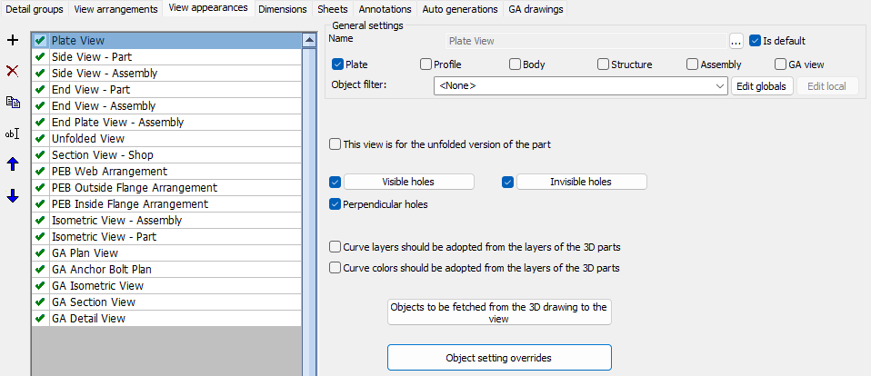
The other options in the dialog box are explained hereafter :
This view is for the unfolded version of the part - When this option is activated then this view will only be used for the unfolded view of a part, if unfolding was enabled for the part, and if the part can be unfolded.
Visible holes - Configure here how visible holes should be displayed, with the ability to choose a different display per hole type
Invisible holes - Configure here how invisible holes should be displayed, with the ability to choose a different display per hole type
Perpendicular holes - Perpendicular holes are holes seen from their side. They would be shown as 2 straight lines and optionally an axis
Curve layers should be adopted from the layers of the 3D parts - Enable this to have all the lines of an object get the same layer color and linetype as the 3D part in model space. This is typically only used on GA views. For more detailed fine-tuning such as giving only an underlayer a certain linetype you should use the Object settings overrides instead.
Curve colors should be adopted from the layers of the 3D parts - Enable this to have all the lines of an object get the same color as the 3D part in model space. This is typically only used on GA views. For more detailed fine-tuning such as giving only an underlayer a certain color you should use the Object settings overrides instead.
Objects to be fetched from the 3D drawing to the view - Configure in the Objects to be copied from 3D to 2D views dialog whether to show : invisible lines, grid lines, bolts, welds, cameras, axii, and hatches on the view
Object settings override - Use the Object settings override dialog to override the visibility of curves on the view. These filters can be created to target objects based on layer, material, structural type, and other properties and geometric characteristics and assign those objects a certain color, linetype, transparency, or have them be skip entirely in a specific view.
Example usages of this are to give an underlayer a grey color, making concrete slabs transparent so the parts behind them are still fully visible, or skipping certain part types from section views to unclutter them.
4 Dimensions
Refer to the Automatic dimensions topic for more information.
5 Sheets
In this Sheets list the order of the items do not influence the sheet generation but they are sortable for the convenience of the user.
The General settings determines which part and assembly types each sheet entry is intended. This will not be used as a filter for the sheet generation but it will be used by the dialog box to determine which detail groups and GA drawings can utilize these named settings.
The other options in the dialog box are explained hereafter :
Format - This option is only used when this Sheets entry is used on a GA drawings group. For part and assembly sheet generation format is decided by the settings in 7 - Auto generations.
Annotation settings - Choose the annotation settings that will be used for this sheet. These annotation settings will also be stored in the sheet itself so that they can still be modified after creation on a sheet per sheet basis. Use the Modify button to directly edit the selected annotation settings.
Sheet properties - This contains the sheet number template and preferences such as LTSCALE, dimension accuracy, angle accuracy, text height for dimensions, and dimension style. These properties are explained in more detail in the Sheet properties topic
Template settings - This contains the frame, bill table, title, and note that should be inserted on the sheet
These settings are explained in more detail in the Template settings topic
Other sheet settings - This contains the clearance between views, between views and sheet edges, between parts, whether to skip a certain hole diameter, whether to skip weld symbols for a certain size, and also the typical weld symbols for reducing the amount of weld symbols on the views
These settings are explained in more detail in the Other sheet settings topic
6 Annotations
In this Annotations list the order of the items do not influence the sheet generation but they are sortable for the convenience of the user.
The General settings determines for which part and assembly types each annotations entry is intended. This will not be used as a filter for the sheet generation but it will be used by the dialog box to determine which detail groups and GA drawings can utilize these named settings.
The Annotations settings allow us to set the Annotation style and optionally override the text height for all the different types of annotations.
7 Auto generations
In this Auto generations list the order of the items do not influence the sheet generation but they are sortable for the convenience of the user.
The General settings determines which part and assembly types each auto generations entry is intended for. This will not be used as a filter for the sheet generation but it will be used by the dialog box to determine which detail groups can utilize these named settings.
The automatic generation of sheets settings allow us to set whether multiple parts are allowed on a single sheet, whether simple parts should be added (uncut, undrilled, unwelded), and which format and scale to be used. Parabuild will attempt to use the first format and scale in the list and if the page is too small it will attempt the next one and continues downwards until it finds a page large enough for the views at the specified scale.
8 GA Drawings
The GA drawing settings are used by the following commands/tools :
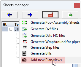

All of these tools will draw one or more new views based on a new or existing camera.
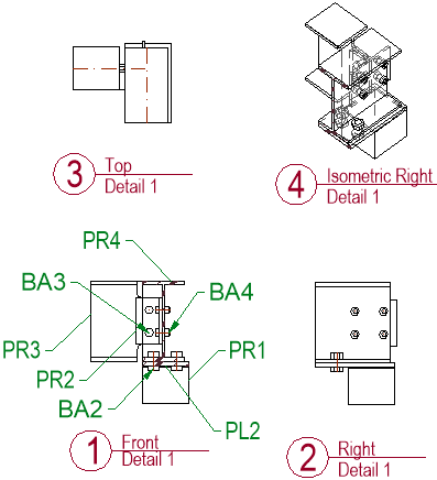
When choosing multi-view detail settings on a detail camera, a typical result looks like this :
All of the above commands will show this view preset selection and annotations dialog box :
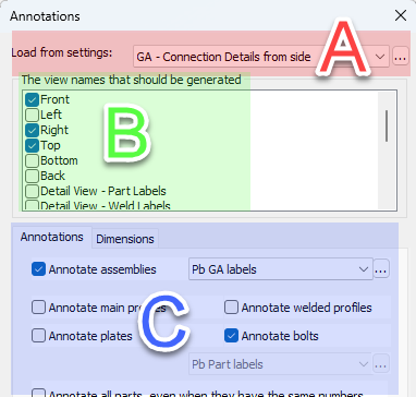
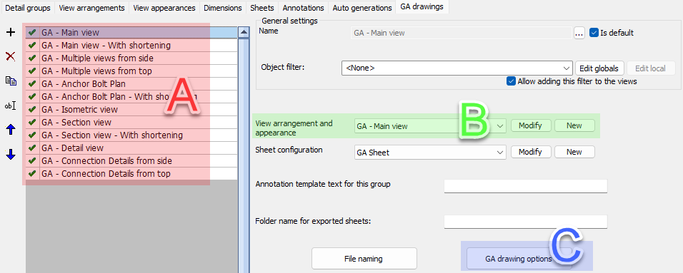
The above dialog can be fully configured with the help of the GA Drawings dialog shown below. The relations are illustrated with areas A, B and C on both dialog images.
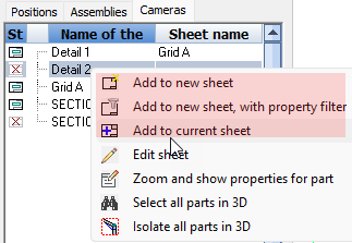
Note when Add to new/current sheet is used on a part or assembly number, then the Detail groups will be shown in the above dialog instead of the GA drawings.
 In this GA Drawings list the order of the entries are only sort-able for the convenience of the user.
A set of GA drawings were pre-created for certain commands or types of cameras such as sections, details and isometric views.
The available options per GA drawing are explained hereafter :
The General settings has the Object filter which can be added to the views that will be created. The object filter is a way to quickly filter out objects that should be shown on the view.
View arrangement and appearance - Choose the views and their appearances that should be shown as an option when one of the above GA tools are started. The user still has the ability to enable or disable some views. Click on Modify to go directly to the chosen settings
Sheet configuration - This contains the sheet configurations such as format, template files and annotation styles. Click on Modify to go directly to the chosen settings
Annotation template text for this group - In case an annotation below the set of views is wanted then this template text can be entered
Folder name for exported sheets - When the sheet is exported as a dwg file or pdf file then it will be written in the provided sub folder name
File naming - Here we can change the sheet name as well as the sub-folder that should be used by the sheets manager.
GA drawing options - Here we can configure the default format and scale, whether the views should be shortened, whether annotations and dimensions should be added. Note that it is possible to enable or disable annotations on a per view basis in the settings B View arrangement and appearance. There we have the Annotation permissions settings which will permit or forbid annotations per view.