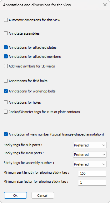
Annotation and dimension permissions
This dialog allows us to allow or disallow dimensions and annotations per type.
Allowing does not necessarily mean that they will be drawn on the view.
The behavior of these permissions depend on the command that is being used to create dimensions or annotations :
- When generating a workshop drawing, the automatic dimensions can be activated or deactivated if the view type supports it.
The same is true for the different annotation types. For example for the main sideviews we would want the dimensions and most annotations activated. For an ISO view we would only want part name annotations to be drawn. - When adding new GA views then the permissions in this dialog are also used, but only for the annotations and dimensions that are activated on the annotations and dimensions tab of the GA view tool.
- The command Automatic annotations and dimensions on view does not follow the permissions in this dialog. As this command only annotates the view that was selected, it will draw all annotation and dimensions that were chosen inside the command, it will only follow the filters in it's own dialog box, and will completely ignore all settings in the dialog box of this topic.
Besides the permissions there are also some filters and preferences for annotations on this dialog box.
We will explore all of the settings in the dialog box :
Automatic dimensions for the view - Enable this if you want the view to receive automatic dimensions. This will only have an effect on support view types such as sideviews and section views
Annotate assemblies - Enable this checkbox if you want to enable annotations for the view. This setting will not have an effect on general arrangement views
Annotations for attached plates - Enable this if the welded plates should be annotated. This setting will not have an effect on general arrangement views
Annotations for attached members - Enable this if the welded members should be annotated. This setting will not have an effect on general arrangement views
Add weld symbols for 3D welds -
Annotations for field bolts - This setting will not have an effect on general arrangement views
Annotations for workshop bolts -
Annotations for holes - This setting will not have an effect on general arrangement views
Radius/Diameter tags for cuts or plate contours -
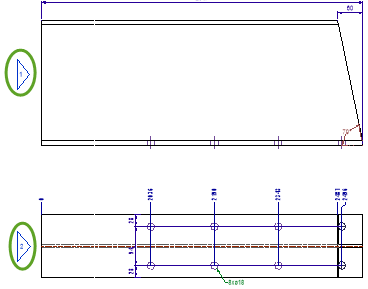
Annotation of view number (typical triangle-shaped annotation) - This setting regulates the triangular annotation next to each side view. We can disable the annotation here without having to remove them from the section view :
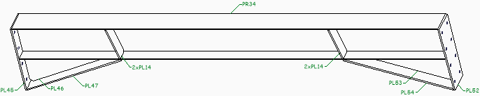
Sticky tags for sub/main/assembly - Sticky tags are tags that will stick to the edge of the annotated part, so that a leader is not necessary.
When activated, Parabuild will automatically decide for each tag whether to make it sticky or not. A tag will only become sticky if the part has an edge that is long enough for the tag to stick to, without intersecting any other lines.
This setting has the following options :
- Never - This disables the sticky tags for this type of object
- Allowed - Sticky tags will be used
- Preferred - Sticky tags will be used as often as possible
|
|
|
An example view with sticky tags disabled |
|
|
|
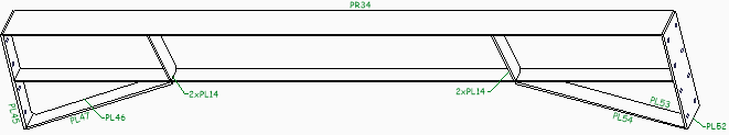
An example view with sticky tags enabled |
Minimum part length for allowing sticky tag - Use this setting to disable sticky tags for small parts
Minimum size factor for allowing sticky tag - Use this setting to skip the sticky tag in cases where the tag is too large compared to the annotated part