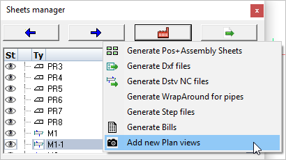
Add New GA views (Plan Views)
With this tool you can create a new general arrangement view based on a grid, a level, an ISO view or the current 3D view.
The new view will be drawn on a new 2D sheet if no sheet is currently active.
Tip If General Arrangement view generation seems slow, then take a look at the topic Sheet generation performance
Activating this command will open the Creating Plan views dialog. Here you may select which view(s) to generate by checking one or more items in the list.
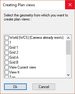
By selecting multiple views you will be prompted to select the position where each view is to be drawn. Unless you've planned exactly where each view is to be positioned within the sheet, this method can lead to some editing of the view placement afterwards.
Placing one view at a time may sometimes be easier. To place one at a time means repeating the Add new plan views process for each view.
After that the Format and scale dialog will appear, enabling you to set the drawing parameters:
The different options in the dialog are explored below :
General tab

Format - Set the size for the new sheet
Scaled to fit - Selecting this option will set the drawing scale to fit the new view.
Scale - Manually sets the drawing scale. The scale will be set as a ratio to 1.
Update project data - When this is enabled during the Refresh Views operation, then the project data inside the title blocks of the sheet will be refreshed as well. The current Project Data of the 3D project will be entered into the title block.
Shorten along the X or Y axis - When enabled, the view will be shortened in X and/or Y directions. This is usually only used on floor plans for laying out the anchors.
Annotations tab
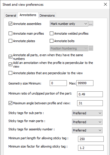
Annotate assemblies - When you activate this, each assembly will automatically receive an annotation. Choose the annotation style for those annotations in the drop-down next to it. More information on the annotation styles can be found at Tools for 2D drawings
Annotate main profiles - When you activate this, each main profile will automatically receive an annotation
Annotate welded profiles - When you activate this, each welded profile (non-mains) will automatically receive an annotation
Annotate plates - When you activate this, each plate will automatically receive an annotation
Annotate bolts - When you activate this, each bolt will automatically receive an annotation
Annotate all parts - When activated, parts that have the same part number will still each be annotated
Geometry size - This options works as a filter for the annotations. Parts smaller than the minimum or larger than the maximum will not receive an annotation. The length of the axis of the parts are used for this filter.
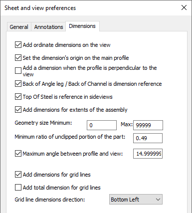
Add ordinate dimensions to the view - Checking this checkbox will add ordinate dimensions to the view.
Add dimension when the profile is perpendicular to the view - Checking this checkbox will add dimensions when the profile is perpendicular to the view - it will not add dimensions when the profile is at an angle to the view.
Back of Angle Leg / Back of Channel is dimension reference - Checking this checkbox will place dimensions from the back (Heel) of the channel or angle.
Top of Steel is reference in side views - Checking this checkbox will make the top-of-steel the reference for placing of dimensions.
Add dimensions for extents of assembly - Checking this checkbox will add O/All dimensions to the view.
Geometry size Minimum - This options works as a filter for the dimensions. Parts smaller than the minimum will not be dimension-ed. The length of the axis of the parts are used for this filter.
Minimum ratio of unclipped portion of the part - Sometimes parts can be drawn partially on a view. This happens when the part is clipped by one of the camera's boundaries. With this setting, you can choose whether clipped parts should be annotated or not.
A ratio of 0.5 means the part needs to be on the view for at least half of it's size. A ratio of 1 would mean that parts that have any clipping should not be annotated at all.
Maximum angle between profile and view - With this setting you can choose whether members that are not drawn flat on the view should be annotated. An angle of 0° means only members drawn flat on the view get annotations.
An angle of 45° could for example be a bracing, or any part in case of isometric views.
Do note that there is another related option in this dialog called Annotate profiles/plates that are perpendicular to the view.
When this option is enabled, and the part is perpendicular to the view, then it will be annotated regardless of this maximum angle setting.
Parts that are exactly perpendicular to the view are often interesting parts to be annotated, and for this reason they can be enabled separately.
Sticky tag options - You can find more about these sticky tag options in the Annotations and dimensions topic.
Dimensions tab
Minimum ratio of unclipped portion of the part - Sometimes parts can be drawn partially on a view. This happens when the part is clipped by one of the camera's boundaries. With this setting, you can choose whether clipped parts should be dimensioned or not.
A ratio of 0.5 means the part needs to be on the view for at least half of it's size. A ratio of 1 would mean that parts that have any clipping should not be dimensioned at all.
Maximum angle between profile and view - With this setting you can choose whether members that are not drawn flat on the view should be dimensioned. An angle of 0° means only members drawn flat on the view get dimensions.
An angle of 45° could for example be a bracing, or any part in case of isometric views.
Do note that there is another related option in this dialog called Add a dimension when the profile is perpendicular to the view.
When this option is enabled, and the part is perpendicular to the view, then it will be dimensioned regardless of this maximum angle setting.
Parts that are exactly perpendicular to the view are often interesting parts to be dimensioned, and for this reason they can be enabled separately.
Add dimensions for grid lines - When you enable this, dimensions between parallel grid lines will be added.
Add total dimension for grid lines - When you enable this, 2 total dimension for parallel grid lines in the X and Y direction will be added.
Grid line dimensions direction - Choose the location of the grid dimensions on the view
Creating views with specific purposes by using the pre-configured views
A simple filter applied to the view such as filtering for a specific phase number can be used as a property inside other filters that query the view.
Filtered objects can also be brought back in the view, with a modified appearance. In practice this means that you can control the appearance and annotations of objects in the view based on what was filtered.
In the below examples the view appearance capabilities are demonstrated and explained with the object override filters.
The following pre-configured views will be explored below :
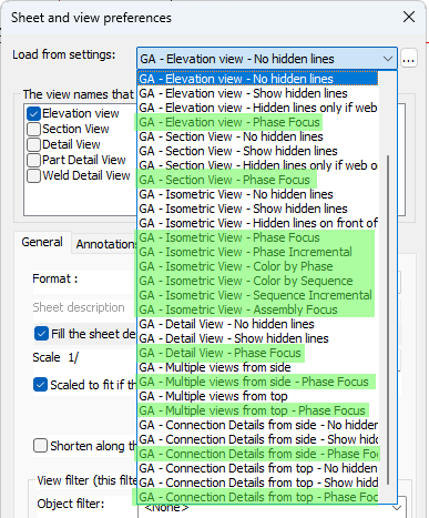
If you do not have these settings entries that may be because you are using settings that were generated by an older version. You could reset all of your settings to the defaults, but if you prefer to keep your current settings then read the instructions on how to Import part of the default settings.
You will have to introduce settings entries on the GA drawings tab as well as on the View arrangements and View appearances tabs.
The above list may be much shorter when you use the tool to draw a new GA view.
That is because the full list of available GA views is filtered based on the camera that you selected. Only the GA views that make sense for the camera's direction are displayed.
Elevation views, plan views, and isometric view directions can be concluded from the camera's direction and that is how the GA presets are filtered.
But you can remove the GA preset reduction by enabling the Show all GA settings : 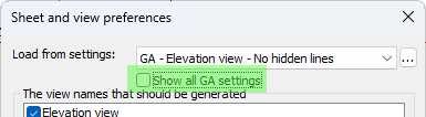
Other view configurations are possible too, either by filtering on other or more properties, or by using other appearance settings.
How views like this can be configured is explained below. To create your own versions of these settings, it might be simplest to adapt an existing one to your preferences.
Note that all the following view styles can be used with any type of camera, so you can use them with isometric views, section views, plan views, detail views or other box-limited views, etc...
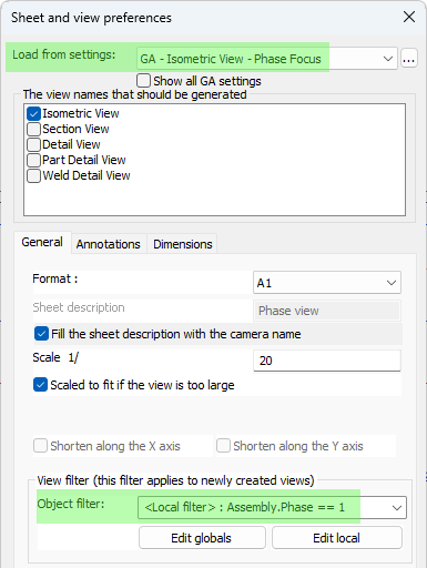
Focus views are useful for highlighting specific parts of the model, such as a specific phase, sequence, material, or any other property or combination of properties. Default Focus views in Parabuild can be created by choosing the "Phase Focus" or "Sequence Focus" settings, and filtering the view for a specific phase or sequence.
Without further object overrides, such a filter would hide all the objects that do not match the view filter. However focus view settings have object overrides that re-introduce filtered objects back into the view, while assigning them a grey color. The below settings show a Phase-based example.
Setting the view filter to a particular phase or sequence is done during creation of the view.
Underneath the view filter setting the object filter is shown. Press Edit Local to change the property value :
Object overrides for the focus views can be found here : 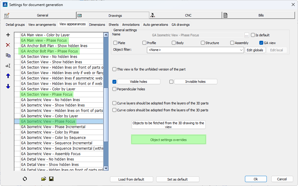
The following override for re-introducing filtered objects was added here :
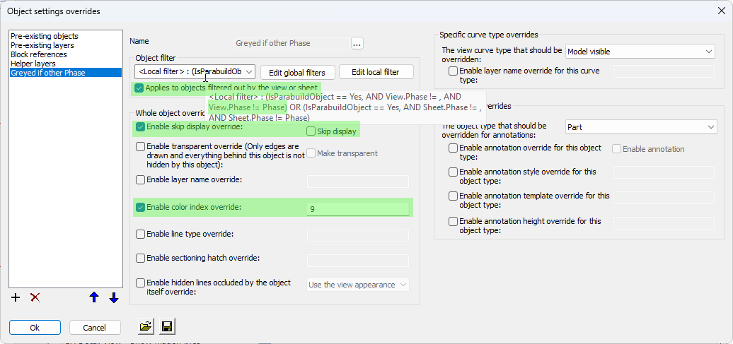
Explanation for the settings in this override:
Local filter - This filter was set to apply only to Parabuild objects, but more important is the filter "View.Phase != Phase" : This means that the Phase of the object can not be the same as the phase of the view to pass this filter. The view phase is retrieved from the phase filter that was set for the view.
Applies to objects filtered out by the view or sheet - By toggling this on we signal that we are looking for objects that were filtered out of the view, so that we can bring them back and change their appearance with this override.
Enable skip display override - Enabling this checkbox together with the Skip display setting turned off makes sure that the objects will be drawn in the view
Enable color index override - Enabling this setting will assign the grey color number (9) to all the objects that are re-introduced back into the view
Incremental views
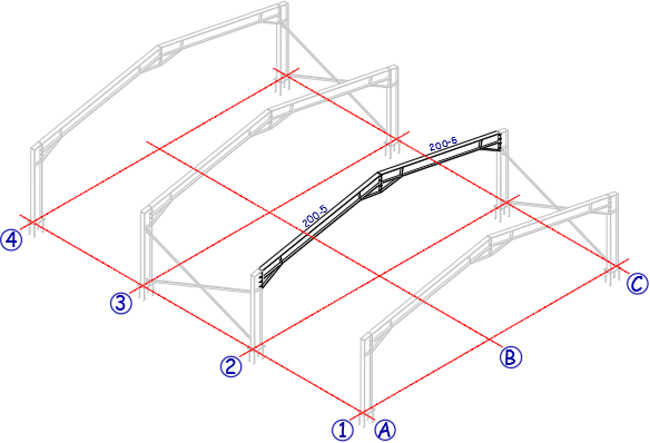
Incremental views are useful for showing erection stepwise based on sequence, phase, or other user chosen properties. In this example sequence that was filtered for is shown as regular geometry, and the earlier sequences are shown as greyed geometry. The parts of later sequences are skipped from the view.
The annotations are configured to automatically annotate only the focused parts and not the greyed parts.
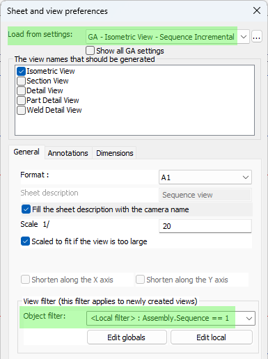
All of these views started from the same GA settings (incremental), they only got a different view filter when the view was created:
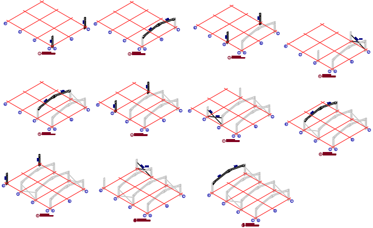
These are 11 incremental views and each one was created separately using the same view settings, but applying a different sequence during creation of the view.
Incremental views are created one by one by choosing a different phase or sequence for each view.
Without further object overrides, such a filter would hide all the objects that do not match the view filter.
However incremental views have object overrides that re-introduce some of the filtered out objects back into the view, while assigning them a grey color. The below settings show a sequence based example.
Setting the view filter to a particular phase or sequence is done during creation of the view.
Underneath the view filter setting the object filter is shown. Press Edit Local to change the property value :
And the overrides for the incremental views can be found here : 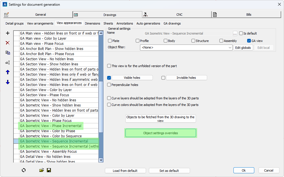
The following override for re-introducing filtered objects was added here :
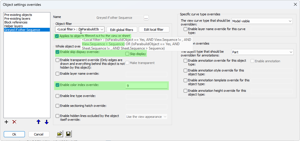
Explanation for the settings in this override:
Local filter - This filter was set to apply only to Parabuild objects, but more important is the filter "View.Sequence > Sequence" : This means that the Sequence of the object needs to be smaller than the sequence of the view. The view sequence is retrieved from the sequence filter that was set for the view.
In other words, we are targeting parts that have a smaller sequence than the sequence of the view.
Applies to objects filtered out by the view or sheet - By toggling this on we signal that we are looking for objects that were filtered out of the view, so that we can bring them back and change their appearance in this override
Enable skip display override - Enabling this checkbox together with the Skip display setting disabled makes sure that the objects will be drawn in the view
Enable color index override - Enabling this setting will assign the grey color number (9) to all the objects that are re-introduced back into the view
Notice that we do not have settings that bring back parts with a sequence larger than the view sequence. This is what allows the incremental display style of successive views, which is the main difference with Focus views.
Occurrence focus view for assembly or GA sheets
This view solution is similar to focus on phase or sequence, but instead the focus is put on a certain assembly number.
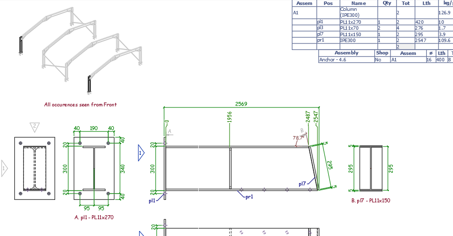
An example assembly drawing with an isometric occurrences view added on top
This view can be added after an assembly sheet has been generated, for cases when the additional context could be useful to the shop floor.
It can also be useful on general arrangement sheets, for providing context during erection.
This is how to add this view to an existing sheet :
- Open an assembly drawing
- Right-click on a camera in the sheets manager, and click on Add to current sheet
- Choose the GA setting GA - Isometric View - Assembly Focus
- If the camera has a isometric viewing direction then choose the view Front. If the camera has a plan/elevation viewing direction then choose one of the Isometric views
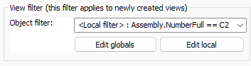
- Note that the occurrence view only works properly if the assembly number is filtered on in the view's filter. When adding the assembly focus view on an existing assembly sheet then this filter is added automatically for you. Just click on Edit Local to change the assembly number if necessary :
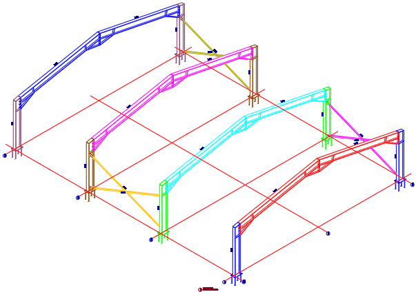
Colored by phase or sequence
Colored views were already possible and can be configured in View Appearance settings by filtering by phase, sequence number or any other property, and then setting a color override.
Examples based on phase and sequence properties were now added to Parabuild default settings to show how this is done, changing the color and annotation based on the phase or sequence of each object.
For the colored sequences you can find the overrides here : 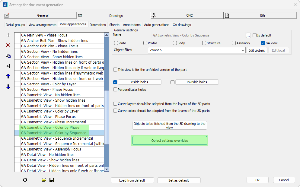
The following settings were set here for each sequence :
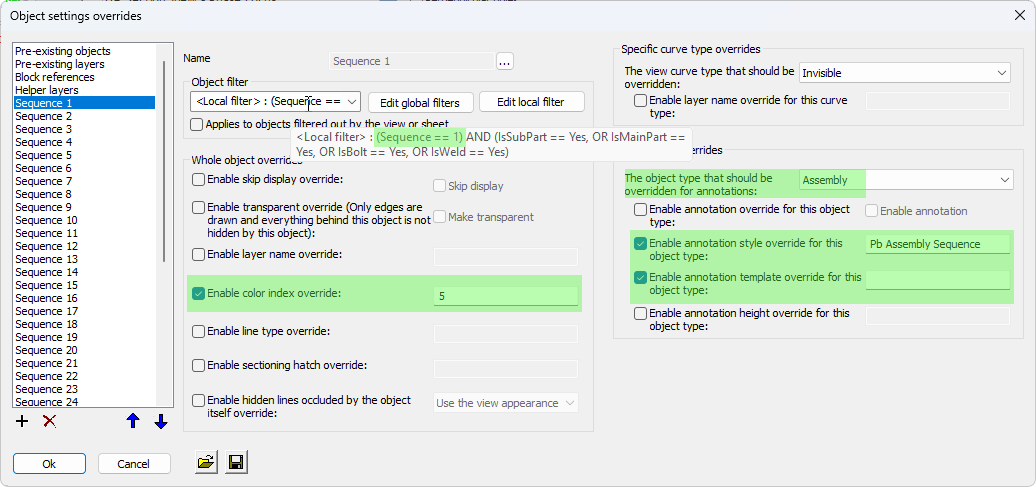
Explanation for the settings in this override:
Local filter - This was set to the sequence number that is being overridden. The sequences from 1 through 40 were created here. If you use a different way of assigning names to the sequences then you will have to change all the sequence names here.
Enable color index override - Enabling this setting will assign the color number to all the objects that have the filtered sequence number or name
The object type that should be overridden for annotations - An override was enabled for assemblies and bolts
Enable annotation style override - The Pb Assembly Sequence style was chosen, so all objects with this sequence will get a sequence annotation
Enable annotation template override - This override was enabled and the template string is empty. This means that the template text that may have been set for this object is removed, ensuring that the Pb Assembly Sequence style's default template string will be used
As you can see there is an override needed for each sequence here. Each override contains the filter on the correct sequence number (or name) and then the color number for that sequence.