Objects to be copied from 3D to 2D views
This dialog box allows us to decide which 3D objects are added to the 2D view.
We can also configure how the translation from 3D to 2D should be done.
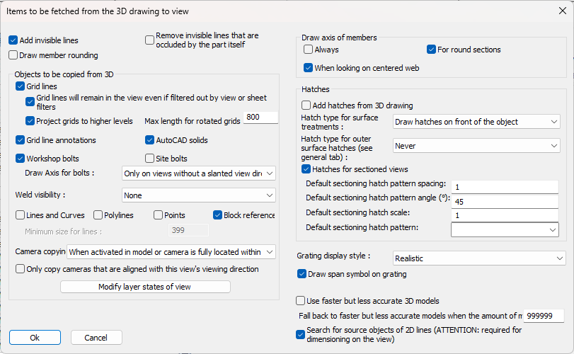
In this dialog box you can change the following options :
Add invisible lines - On workshop drawings, these lines should always be drawn. But on 3D views or GA views, the invisible lines will quickly overcrowd a view.
Remove invisible lines that are occluded by the part itself - By activating this, many of the hidden lines are cleared, uncluttering the view.
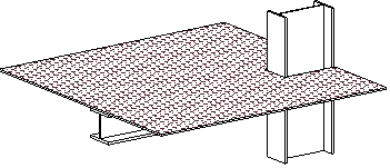
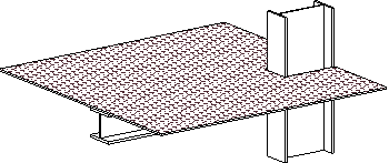
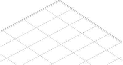
To illustrate the differences between all of the hidden line options, here are examples of the 3 different hidden line options that are available :
|
|
|
|
|
All hidden lines disabled |
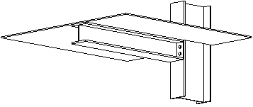
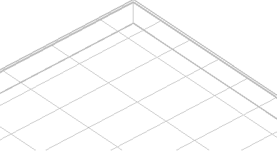
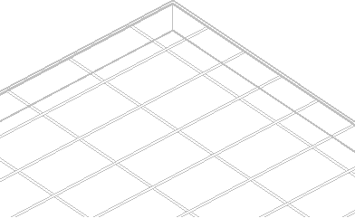
All hidden lines enabled |
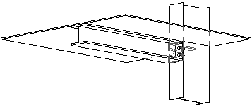
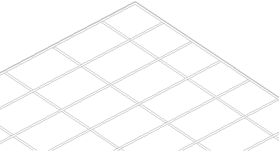
Hidden lines are enabled and the new 'skip occluded by self' option as well |
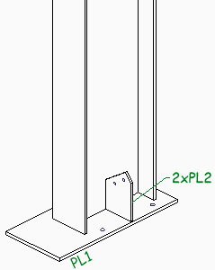
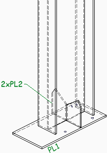

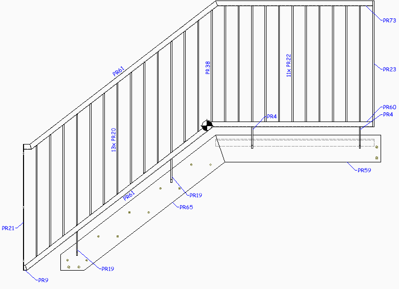
With the hidden lines option active, we can see the part behind the column.
With the occluded by self option active, most of the clutter of invisible lines will be cleared while still keeping hidden parts visible.
This option will be very useful for the 3D isometric view on shop drawings.
The new hidden line method will help clarify the assembly's composition.
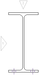
Draw member rounding - This option enables or disables the rounding on a select number of standard sections.
|
|
|
|
Example 2D view with member rounding disabled |
Example 2D view with member rounding enabled |
Draw center of gravity indicator on view and Indicator size - The COG symbol will be drawn like this :
The indicator size is in sheet units so this will be adapted automatically based on the sheet scale.
Grid lines - Enable this option to copy grid lines to the 2D view
Grid lines will remain in the view even if filtered out by view or sheet filters -
Project grids to higher levels - When enabled, the grid lines on the 'floor' will be copied to higher levels, even if the floor falls out of scope of the view.
Max length for rotated grids - Thanks to this option, elevation views will get grid lines.
Use this option to set the size of these 'rotated' grid lines.
Set this value to 0 to disable grid lines on elevation views all together.
Grid line annotations - This option causes the grid lines to automatically get grid line annotations on the view.
AutoCAD solids - When enabled, AutoCAD 3D Solids will be shown in the view
Workshop bolts - Typically, workshop bolts are shown on both the shop drawings and on the GA views
Site bolts - Typically, site bolts are not shown on the shop drawings
Draw Axis for bolts - When enabled, a red axis will be drawn for the specified bolts
Weld visibility - This setting has the following options :
- None -
- Curve -
- Volume -
Lines and curves/Polylines - When enabled, lines/polylines that are drawn in 3D will also be copied to the view.
This option has no effect on workshop drawings because the workshop drawings are not based on a camera. Instead they work based on a part number filter.
Minimum size for lines - If a line is smaller than the size entered here, then the line will not be copied to the view. This option was created to overcome performance problems that happened with large drawings that contain many small lines. 2D drawings that act as an underlay will often contain many of these lines.
Points - When enabled, points in the 3D model will be included in the view
Block references - When enabled, block references in the 3D model will be included in the view
Modify layer states of view - To specify in advance which layers in the 3D model to be on or off for the view.
Any layers not listed here but that do exist in the 3D model will get the current layer on/off state from the 3D model at the time of view creation.
Camera copying - This setting has the following options :
- Never -
- When printing is activated in model space camera -
- When activated in model or camera is fully located within the view -
- When activated in model or camera is partially located within the view -
Only copy cameras that are aligned with this view's viewing direction -
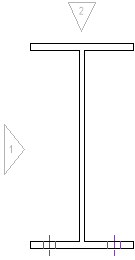
Draw axis of members - This setting will draw the red axis line for members.
It has the following options :
- Always -
- For round sections -
- When looking on centered web -
Hatches
There are 4 types of hatches that can be enabled, they are explained here :
Add hatches from 3D drawing - When enabled, hatches in the 3D model will be included in the view. These hatches will also be clipped by the view. This concerns only hatches drawn in the 3D model and has no influence on the hatches that may be drawn by Parabuild for the representation of surface treatments and grating. Those are not separate objects but they are integrated inside plates and profiles, and are controlled using the settings below.
Hatch type for surface treatments - Surface treatments are different from outer surface hatches so take note not to confuse them. A surface treatment is usually activated on a surface of a part to indicate that that surface should be shown and treated differently from all the other surfaces of the object. An example is a raised pattern floor plate, which should have the raised pattern on the top face of the plate and this information will be used by the Parabuild numbering system and shown on 2D views.
This setting determines how the surface treatments of 3D objects should be shown in the 2D view.
The 3 possible options are shown here with result examples.
- Never : Surface treatments are never shown on the 2D view
|
|
|
|
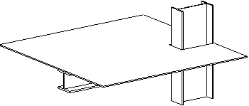
A floor plate as drawn in the 3D model |
The result on the 2D view : the surface treatment is not drawn |
- Draw hatches on front of the object : When looking at front of the surface treatment then the treatment will be drawn. But looking from the back side of the surface treatment then the treatment will never be shown
|
|
|
|
|
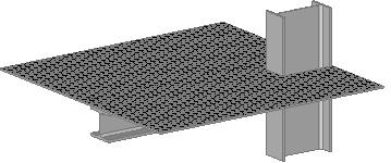
The surface treatment of the floor plate is shown when looking at the front of the treatment |
The surface treatment of the floor plate when looking at the back of the treatment |
The surface treatment of the floor plate when looking at the back of the treatment with hidden lines active |
- Draw hatches on front and back of the object : The surface treatment will be shown when looking at the front and the back of the treatment. Note that for the back of the treatment to be shown hidden lines need to be activated as well, otherwise the back setting has no effect since the hatch will be hidden.
|
|
|
|
The surface treatment of the floor plate is shown when looking at the front of the treatment |
The surface treatment of the floor plate when looking at the back of the treatment. Hidden lines needs to be activated for this to have an effect |

Hatch type for outer surface hatches - Outer surface hatches are different from surface treatments, so take note not to confuse them. The outer surface hatches are defined in the hatch settings on the general tab. We can assign an outer surface hatch to objects based on any filter. This setting works the same way as "Hatch type for surface treatments".
Unlike surface treatments however, outer surface hatches are added automatically on 2D views instead of specified in the 3D model. In addition to this setting in the view, this requires setting up your automatic hatches in the general tab of the Parabuild output settings. Filtering can be based on any combination of properties, for example allowing you to specify a hatch for all solids on a specific layer. Remember that a hatch is a planar object, so hatches will not be applied to curved surfaces.
In this practical example we added an outer surface hatch for all the objects that have the material Brick :
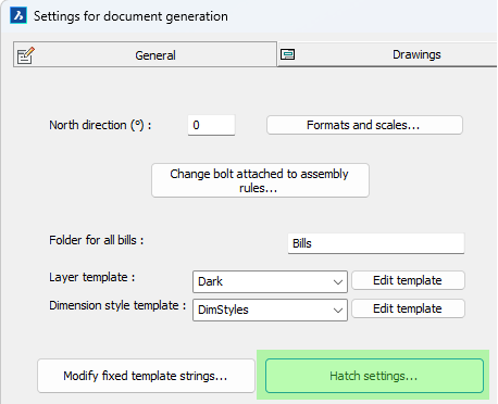
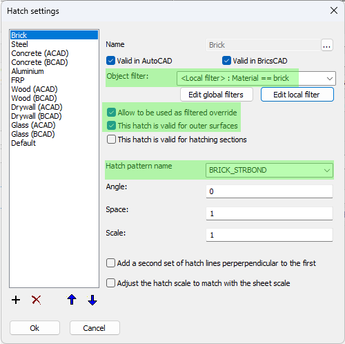
The necessary settings for the brick hatch on objects that have the Brick material are highlighted
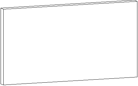
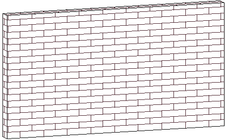
And these are the results with or without the above hatch setting :
|
|
|
|
This is a wall object without any material assigned |
This is the wall object with the brick material assigned to it. Note that all visible external surfaces will get the same hatch pattern |
Hatches for sectioned views - Enable this to draw hatches whenever a part is clipped by the view's clipping faces. This requires setting up your automatic hatches in the general tab of the Parabuild output settings, similar to outer surface hatches.
Default sectioning hatch patter spacing, angle, scale, and pattern - Choose the default hatch configuration for sectioned objects. These hatch settings will only be used when there is no hatching configuration done for the 3D object. On the general tab the hatches are already configured for the most common materials, it is recommended to adapt those to your preferences.
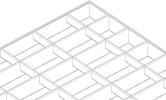
Grating display style - This will influence how grating is drawn in the 2D view. Parabuild settings of some view types have grating appearance set to lightweight types, such as hatched for large isometric views, and others set to full detailed grating for example in detail views. Be sure to adapt those settings to your preferences.
There are the following display styles to choose from :
- None - The grating will not be drawn, only the outline of the plate will be visible with an optional span direction symbol.
- Simple hatch - The grating will be represented by a simple hatch : 1 line per bar
- Simple hatch see through - The grating will be represented by a simple hatch : 1 line per bar. Everything behind the grating plate is drawn as if the grating plate does not obscure anything behind it. If there are any edge bars, they are drawn in full.
- Real hatch - The grating will be represented by a hatch that shows 2 lines per bar.
- Real hatch see through - The grating will be represented by a hatch that shows 2 lines per bar. Everything behind the grating plate is drawn as if the grating plate does not obscure anything behind it.
- Continuous plates - In this style the grating bars are drawn, but they are colliding with each other. This causes less lines to be drawn and the bar intersections are not exactly drawn according to drafting rules. This makes the creation of views slower if there is a lot of grating, but is still faster than the 'Realistic' option.
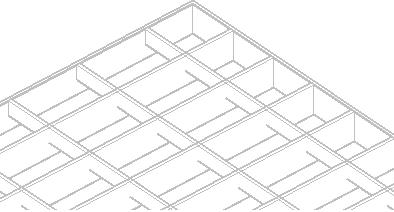
- Realistic - In this style the grating bars are fully detailed with intersecting lines where bars cross each other. This will take the most time when creating views with a lot of grating.
Combining surface treatment on top of grating and sectioning of detailed grating representations are also supported for 2D views.
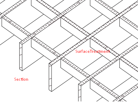
This is an example that combines some of the new 2D view capabilities : 1) Grating is drawn in full detail 2) The grating is clipped and the section hatches of the grating bars are drawn 3) The top surface has a surface treatment and only the top faces of the grating bars receive the surface treatment hatches in 2D views
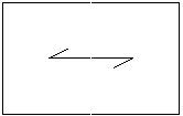
Draw span symbol on gratings - When enabled, grating panels will get a span symbol on 2D views. The span symbol indicates the direction of the load bars :
Use faster but less accurate 3D models - If you activate this option then the Parabuild 3D models will be used for the generation of the 2D views. Arcs will be drawn tessellated with short straight lines. Use this option only if you are experiencing difficulties with the option deactivated.
Fall back to faster but less accurate models when the amount of models exceed -
Search for source objects of 2D lines - This option must be activated for measuring of levels, for measuring shortened view and for the adjusting of dimensions and annotations when the view is refreshed. Thanks to this option the dimensions are measured in 3D, not in 2D.