General output settings
This topic explains the settings on the General tab of the Document generation Settings dialog box.
Selecting the General tab will open the following dialog:
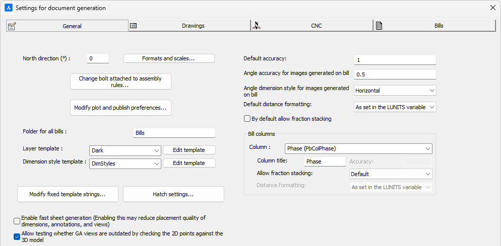
The options that pertain to all sheets and all bills instead of just a subset are collected here.
All of the options on this dialog are explored below :
North direction (°)
This option is simply a shortcut to the NORTHDIRECTION variable of the 3D drawing.
The shop drawings can optionally use the cardinal directions for views. Parabuild uses the current drawing's NORTHDIRECTION variable to know this direction.
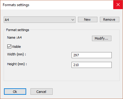
This dialog box allows you to add more formats that can then later be used by Parabuild for the generation of sheets.
Do note that after adding a new format, you also need to create a new sheet template drawing that should be used in combination with the new format. The name of this sheet template drawing should exactly match the name of the format. You can find out more about the sheet templates and their location in the Settings for page and layout.
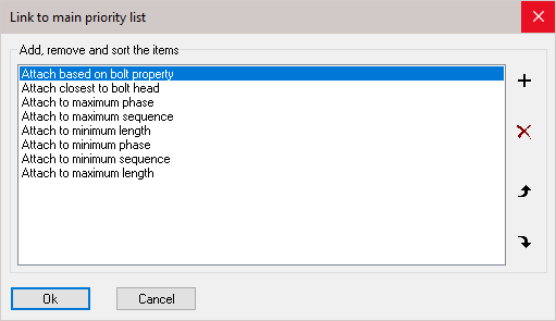
Change bolt attached to assembly rules
With this priority list you can influence the automatic assignment of reference assembly of all bolts. The list is ordered according to priority. You can add, delete, and sort all items in the list.
In exceptional cases where the automatic choice taken by Parabuild is not as desired, it is still possible to manually set the reference assembly in the properties of the bolt:
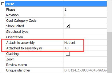
The property Attach to assembly allows you to override the main priority list for the bolt by choosing Closest to bolt head or Closest to Bolt end.
The property Attached to assembly nr can't be changed. This will indicate which assembly the bolt is currently attached to. It is the assembly that was effectively chosen by the either the main priority list or by the Attach to assembly property if it has been set.
Plot and publish preferences
When you click on the button, the following dialog box is shown :
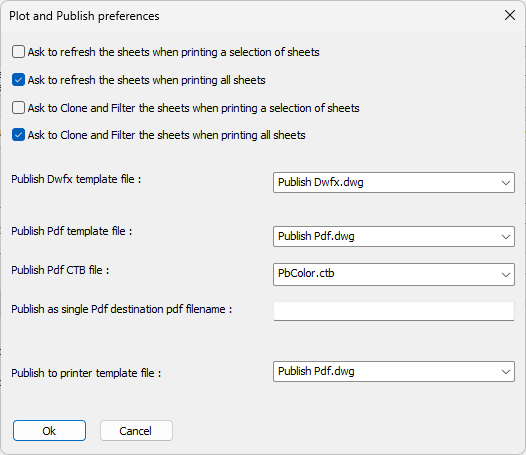
Each setting is explained hereafter :
Ask to refresh the sheets when printing a selection of sheets - Enables or disables the Refresh sheet question when printing a manual selection of sheets with a Right-click on 2D sheets
Ask to refresh the sheets when printing all sheets - Enables or disables the Refresh sheet question when Printing all sheets
Ask to Clone and Filter the sheets when printing a selection of sheets - Enables or disables the Clone and Filter question when printing a manual selection of sheets with a Right-click on 2D sheets
Ask to Clone and Filter the sheets when printing all sheets - Enables or disables the Clone and Filter question when Printing all sheets
Publish Dwfx template file - When publishing a Dwfx file per part or per assembly, Parabuild needs to use this template drawing that is virtually empty.
The part or assembly (and sheet) that are to be written to the Dwfx will be inserted into this template drawing's model space.
After that the template drawing is exported as a Dwfx file with he name of the part or assembly to complete the process.
The layouts inside this template drawing are not used at this time.
When exporting the entire model into a single Dwfx file then this template file will not be used.
Publish Pdf template file - When publishing Pdf files, Parabuild needs to use this template drawing that is empty except for pre-created layouts.
The template drawing is used again for each sheet that is published. The sheet that is to be written to Pdf will be inserted into this template drawing, on the layout that has the same name as the sheet's format name.
So the template file needs to contain the same amount of layouts as there are formats in Parabuild, and the layout names need to exactly match the format names in Parabuild, otherwise the publish will not work for all formats.
The device and media name that are set in the layout inside the template will be used except if the user overrides them during the publish action. That is also why we can use the Publish Pdf template for publishing to a physical printer : the device name is overridden with a local printer name chosen by the user in the print tool at the last moment before the publish action is started.
The publish template file that is included in the Parabuild installation was configured for all default formats so this template can be used as a basis to create your own custom template with different print options or formats if that is needed.
Publish Pdf CTB file - When publishing a set of sheets to a single PDF file through Right-clicking or the Printing all sheets method, this CTB file will be used. These 2 publishing methods do not ask for the CTB file so this is the only place where the choice can be changed.
Publish as single Pdf destination pdf filename - When this option is empty, Parabuild will ask for the filename in a dialog box each time that such a single Pdf file is produced.
When you enter a text field here then that text will be used for the Pdf filename (and overwritten each time).
The prompt for saving the Pdf filename will not be shown in this case.
This text field may contain the following variables between %% :
- Project settings such as %Project_Name%. The list of fixed project data are listed in the Template settings topic.
- %PrB_3DFoldername%
- %PrB_3DFilename%
- %PrB_Date%
- %PrB_Time%
- %language%
- %outputLanguage%
Publish to printer template file - When publishing to a printer device, Parabuild needs to use this template drawing that is empty except for pre-created layouts.
This works exactly the same as the publish to Publish Pdf template file so refer to that option above to learn how the template file is used.
It would be possible to create your own printer template file in which the device names and media names was pre-configured in each layout inside the template file. However, the device name can be different on each machine while the template file is located in the Parabuild library which can be used on different machines.
We would advise against this workflow and instead override the device name in the print tool's dialog box, which also allows saving the device name as default. In the print tool's dialog box the default that you save there is saved locally on the computer, which is perfect for printing to a device!
Folder for all bills
The bills will always be generated under the same folder as the main dwg file but additionally under a sub folder that has the name of the dwg file.
And then also another optional sub folder that is specified here.
When the dwg of the project is c:\drawings\supermarket.dwg and this optional bills folder is Bills then the folder where all bills are stored would be :
c:\drawings\supermarket\Bills\
Layer template
Choose the layer template that you want to use for all the sheets.
This layer template will be inserted automatically when they are needed, for example when the first workshop sheet or GA sheet is created.
The 2 out-of-the-box layer templates include all of the different layers that are used by views, annotations and dimensions on sheets :
- Dark : this template was made for a light background
- Light : this template was made for a dark background
Besides the colors on screen the purpose of the templates is also to set the dashed and dashdot line types for some lines.
And also more importantly these layer colors work in tandem with the CTB files that are also distributed with Parabuild.
Whenever a sheet is printed with a Parabuild, AutoCAD, or BricsCAD command we have the option to choose a CTB file : 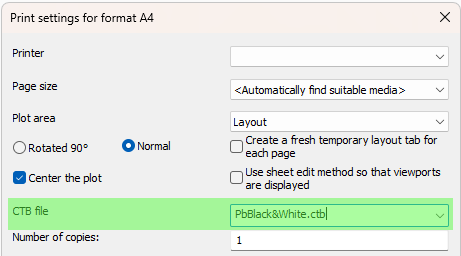
The CTB file translates an object color in your model into an object color + lineweight on the page.
The available default CTB files are the ones distributed with AutoCAD or BricsCAD, but these 2 defaults are also distributed with Parabuild :
PbBlack&White.ctb and PbColor.ctb.
These 2 Parabuild defaults are set up to either print with the same colors as they are on screen, or with black&white only.
Besides the colors these files also determine the lineweight of each color. By default the visible model lines are printed a little thicker than all other lines.
You can review or create your own CTB file with the command _StylesManager in AutoCAD or BricsCAD.
These 2 default Parabuild CTB files are stored in the correct AutoCAD or BricsCAD folder so that all the print commands can find the file.
This folder is different for AutoCAD and BricsCAD and even different for each version.
To make things easier for us Parabuild will copy all of the CTB files in this folder into the AutoCAD or BricsCAD CTB folder each time that Parabuild is loaded :
\Pb_Lib\Default template files\CTB (Color dependent tables for plotting)\
The purpose of this folder and the other folders in the library are explained in the Parabuild library folder topic.
Dimension style template
Choose the dimension style template that you want to use for all the sheets.
This template will be inserted automatically when they are needed, for example when the first workshop sheet or GA sheet is created.
This template file will only contain 2 dimension styles for all the automatically drawn dimensions on sheets : PrB_GADims and PrB_WorshopDims.
Modify fixed template strings
These fixed strings allow you to configure the contents of custom bill columns. This offers a solution when you need to have a column contain custom contents such as project data or even multiple properties combined. We can enter between %% any bill column name, or property, or query.
Other than the data itself it is also possible to add Expressions and functions in this field to manipulate the data itself.
Below in red an example template string where the project number and project name are configured as contents for fixed template column 1 :
%Project_Number% %Project_Name%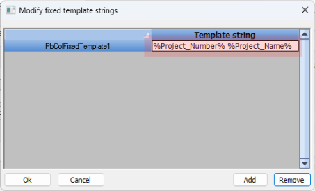
In order to use this column in a bill all you need to do is activate the column PBColFixedTemplate1 in the bill.
We can only change the contents of the template and not it's name.
That is because only the named columns PbColFixedTemplateX from 1 through 10 can be enabled for columns in all the bills.
The bill columns do not support custom named columns. This dialog gives us a way around this limitation, allowing you to create columns with virtually any contents the same way that annotations allow.
The column title in the bill itself will be Fixed1 through Fixed10. But you can change these titles in this dialog in the Bill columns section.
Project data
All Project Data both fixed and custom data, can be used here too by setting the project name between %%. For example : %Project_Name%
All the fixed project data items are listed in the Template settings topic.
Dynamic properties
Dynamic properties are custom properties that you can create yourself for when you need more properties than the defaults offered by Parabuild.
The name of the dynamic property should be set between % symbols inside this template string. For example : %MyCustomPropertyName%
Expressions and functions
We can use expressions and functions in this string to make the resulting text very flexible by using calculations on the variables such as + - / * and also the IF statement to make the string different based on a condition of the part.
Read more about this in the Expressions and functions topic.
Macro values
There is a query variable called MacroVariableValue which can be used here too. This is an example :
%(%MacroVariableValue.Bolts.Pattern.Count1%*%MacroVariableValue.Bolts.Pattern.Count2%)% x %MacroVariableValue.Bolts.BoltAssembly%
The above text field could result in : 4 x Anchor rod
The variable retrieval is shown in blue, expression information is shown in red, and static text is shown in green.
The MacroVariableValue query will search for the macro that owns the annotated part or part in the bill, and will return information from that macro.
The MacroVariableValue query uses the same naming rules as the excel feeding mechanism to extract variable data from the macro and it's modules. Refer to the excel feeding topic to learn how to set the names in this query.
Hatch settings
This dialog allows us to change the hatch patterns that all views should apply to certain 3D objects :

The hatch settings in this list work as a filtering list.
When the hatch pattern of a 3D part needs to be determined during view generation, Parabuild will start from the top of this list and apply the hatch settings if the filter is a match for the current 3D part.
The order of the items will thus influence the decision making.
The purpose of each setting is explained below.
Valid in AutoCAD/BricsCAD - These 2 filters allow us to make the hatch setting available in BricsCAD only, AutoCAD only, or both. The reason for having this is because the hatch names for concrete, wood, drywall, and glass are different in AutoCAD vs BricsCAD.
Object filter - Determine here which parts should get the current hatch settings using the Objects filtering tool
Allow to be used as filtered override - Enable this if the current hatch settings should be used by 2D view generation.
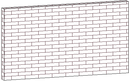
This hatch is valid for outer surfaces - When enabled, this hatch applies to all of the outer surfaces of the part. Here is for example a brick wall :
This hatch is valid for hatching sections - When enabled, this hatch applies to the inner material that is sectioned by the view. For example concrete and steel :
Hatch pattern name - This is the AutoCAD or BricsCAD hatch pattern name that should be used
Angle - Specified the angle at which the pattern should be drawn
Space - Specifies the spacing between simple hatch lines
Scale - Specifies the scale that should be applied to the hatch pattern. A value of 1 is no change, and a value of 2 would double the size.
Add a second set of hatch lines perpendicular to the first - This will create 2 of the same hatch patterns but perpendicular to each other
Adjust the hatch scale to match with the sheet scale - Enable this if you want the hatch to be scaled together with the sheet scale. When it is disabled the hatch will be solely based on the 3D model size, which can cause very small hatch sizes when the sheet is scaled.
When this is disabled the hatches may even fail to be drawn because hatches have a maximum number of lines to protect against freezing the program.
It is therefore recommended to enable this for reliable hatches on sheets.
Enable fast sheet generation
The fast generation mode will speed up the generation of shop drawings. Less time will be spent on finding the best location for dimensions, annotations and views. The resulting quality may be less when this is active especially on large views that have many dimensions and/or annotations.
Allow testing whether GA views are outdated by checking the 2D points against the 3D model
This option can detect whether a GA view is outdated or not. The GA view will be barred like the views on shop drawings when any of the points in the view do not match up with the 3D model counterpart locations.
Unlike shop drawings the barring on expired GA views will not be printed. They are there as a warning for the drafter only.
Note that this is an experimental feature and it will return false positives and will not detect all the changes such as newly added objects.
Default accuracy
This default accuracy applies only to the bill columns used by bills : when the accuracy could not be retrieved from the bill columns list lower in this dialog, then Parabuild will fall back to this default accuracy for rounding the distance.
Angle accuracy for images generated on bill
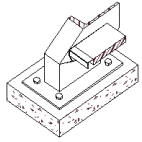
This accuracy relates only to Bills that include an image of the saw cuts of a profile.
The default bill that has these images is called Cutting list with images and looks like this :
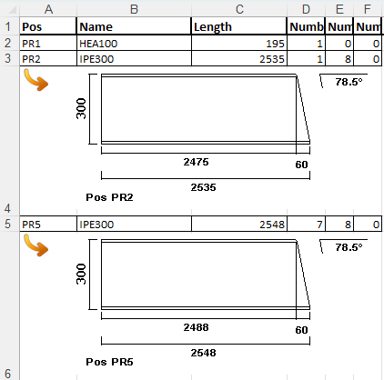
This setting allows you to change the rounding of the angles on these images.
Angle dimension style for images generated on bill
This relates to the same images on bills as above.
Choose the bases to which the angles should be measured on the image with this setting.
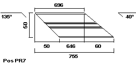
This is an example image result that was generated with the option Horizontal, always top side
Default distance formatting
This variables only relates to fractions and feet & inches notations in all bills.
When the distance formatting could not be retrieved from the bill columns list lower in this dialog, then Parabuild will fall back to this default formatting of distances.
The available formatting options are the same as the ones offered by the AutoCAD LUNITS variables.
However there is 1 additional option called <As set in the LUNITS variable> and when this option is chosen then the LUNITS value of the current main dwg file will be used.
By default allow fraction stacking
This variables only relates to fractions in all bills.
When this fraction setting could not be retrieved from the bill columns list lower in this dialog, then Parabuild will fall back to this default fraction setting.
When stacked fractions is enabled the fractions will be drawn as  instead of 1/2
These options allow you to configure the bill columns used in the regular Bill of materials but also in the bill tables that are shown on all 2D sheets.
You can change the column title for each property, which is often used to enter a shorter word to reduce the column's width requirement.
For columns that contain numerical values, you can set the precision value - i.e. 0.5 / 0.1 / 0.01 etc...
For fractions and feet&inches notations you can also choose the formatting to be used per column.
Stacking of fractions ( ) can also be enabled here per column.