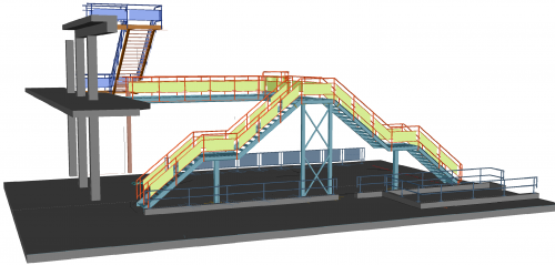
General Arrangement drawings
Use the 3D structural steel model to create general arrangement drawings (GA drawings); anchor bolt plans, side views, floor plans, 3D views, sections, … Use filters and view limits to your advantage to quickly create the result you need.
Linked 3D model and 2D drawings
Each 2D section or detail is linked to the 3D model. When the 3D structure was changed, the general arrangement drawings are tagged as out of date and can be updated with a click of a button. Parabuild will get the latest info from the 3D structure to update the views and BOM. In doing this, Parabuild will keep your existing dimensions and annotations intact. When a part has moved or changed, any dimensions or annotations that refer to that part will be updated so that it measures the new location of the part.
Native DWG drawings
All generated drawings are stored in the DWG format, the most common and widely used format for 2D drawings. You can choose to keep the shop drawings in the same drawing as the 3D model, or as separate drawings
Native AutoCAD/BricsCAD dimensions
Unlike other steel detailing software Parabuild draws automatic dimensions directly with the native types provided by AutoCAD and BricsCAD. This makes your life a lot easier when editing drawings!
Convenient dimension tools
Parabuild provides tools to draw and edit chain and ordinate dimensions more efficiently than AutoCAD’s tools. We make sure you can draw chain and ordinate dimensions with minimum effort, even for oblique dimensions.
Annotations 
Parabuild can automatically draw annotations on your GA drawings. You can also add annotations manually using the flexible tools that we built for this purpose. These are some of the annotation types that are available by default : Assembly nr, Position nr, part name, level, hole diameter, hole data, comment, … The tool is flexible so it allows you to create your own annotation types.
Straight from the 3D model
Because Parabuild retrieves the parts and assemblies straight from the 3D structural steel, the GA drawings are accurate and detailers can rely on the information in the 2D details. This avoids many fabrication and erection problems and errors!
Flexible drawing BOM
The drawing BOM is a standard table and is fully customizable. Designing your ideal bill in a DWG template file is very easy, and the location of the bill in the detail drawing can be changed. The content in the BOM is sourced directly from the 3D structure.
Sections and details
You can create a new detail, section or overview from within the 2D sheet or from the 3D model. Views and sections can be manipulated in the 3D model using the camera object.
Some of the additional camera tools :
- Simple front/back view limitation
- Box view limitation
- Exclude some layers
- Exclude/isolate some objects
- View appearance settings such as Hidden lines, Axis, Holes, hatching, …