Workshop Drawings
Workshop Drawings
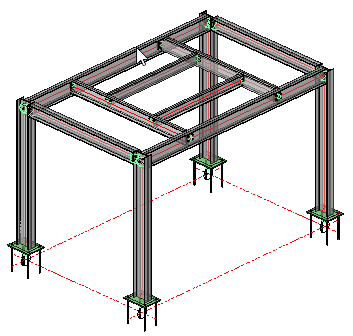
From the simple model just created we will now produce the workshop drawings which will include:
Position and assembly sheets - which are piece by piece workshop details of all the component parts of the structure, together with assembly details, detailing how the component parts fit together to form the assembly - an example would be a beam with end plates welded to one, or both ends. Each part will be automatically given a part number, and each assembly will be automatically numbered, referencing the individual part numbers.
Parabuild allows you to edit and customize each of these functions - which we will look at as this chapter progresses.
Generate DXF files - which are AutoCad Data Exchange Files. These files may be read by virtually all CAD formats. Parabuild produces DXF files for all workshop drawings by default. (For more details on Generating DXf Files go to Generate DXF files)
DSTV NC files - to be read by most cutting- and drilling CNC (Computer Numerically Controlled) machines. Also some plate machines (laser, plasma) (For more details on generating DSTV NC files go to Generate DSTV NC files)
Generate WrapAround for pipes - this function will provide numeric details for the cutting of pipes or circular hollow sections which a welded together to form a joint - this is useful when detailing hollow section girders or trusses. (For more information on this go to Generate WrapAround for pipes)
Generate STEP files - which is a CAD file format, usually used to share 3D models between users with different CAD systems (For more information on this go to Generate STEP fies)
Generate Bills - which include comprehensive bills of material, bolt lists, washers etc.
General arrangement Drawings - where you are able to produce 2D plan and elevation views of the structure. These will be based on the already established grid-line formation and set levels.
Position and Assembly Sheets
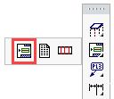
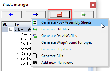
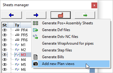
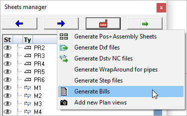
We begin by opening the Sheets manager from the Main - Output menu. Press the Generate button to open the drop-down options, and select Generate Position+Assembly Sheets
Following the procedure given in Generate Position+Assembly Sheets the sheets will be prepared and stored (In DXF format) in the same folder as the model.
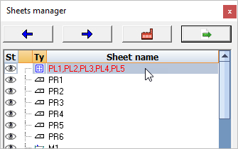
The Position and assembly sheets may be reviewed by double clicking the item in the top list of the Sheets Manager, or alternatively, you may use the left / right arrows to scroll though the drawings.
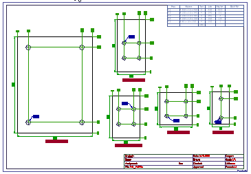
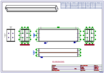
As can be seen from the examples below, Items and assemblies are automatically fully dimensioned and marked.
The drawing sheets contain a schedule of materials and title block - all of which can be modified and customized to suit your particular requirements. The examples shown below have been prepared according to the default values determined by the Settings. We'll look at reviewing these settings and making some changes:
|
|
Typical Detail Drawing |
Typical Assembly Drawing |
Dimensions and Annotations
Setting values for automatic dimensioning is in 2 parts:
Part 1 includes setting the Sheet properties, where you may set (among other things) the dimension and text styles
Part 2 includes setting the format of the dimensions, where you may establish whether the dimensions are Ordinate (as above) or Chained - you may also set the dimension positions relative to the object. These Default Dimension values are set separately by means of interactive dialogs for Plates, Side views, and Sections
Modify Frame templates
Here you may select and/or modify the drawing frame template (Sheet size) by selecting from any of the ISO or US frame templates. Go to Modify Frame Templates
Modify Title Block template
Here you may edit the title block by adding Project titles, signatures, etc. You may also edit the title block to show your, or your company's logo and information. Go to Modify Title Templates
Modify Bill of Material Template
Here you may edit the Bill of material template by adding or deleting columns, rearranging them, and inserting additional data. You may also change its position in the drawing sheet. Go to Modify Bill Templates
Manually Editing the Drawings
Parabuild has many functions for manually adding additional information to the assembly drawings - these include Weld symbols, Levels, Comments, Additional annotations, Part names etc. These options can be found at Tools for 2D Drawings
General Notes
Here you can add generic General Notes to drawings. Parabuild has a built-in General Notes template which you may complete and add to the drawing frame. For more information go to the General Notes Template
General Arrangement Drawings
We begin by opening the Sheets manager from the Main - Output menu. Press the Generate button to open the drop-down options, and select Add new Plan views
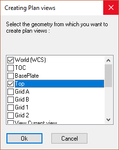
Follow the procedure given in Add new Plan Views
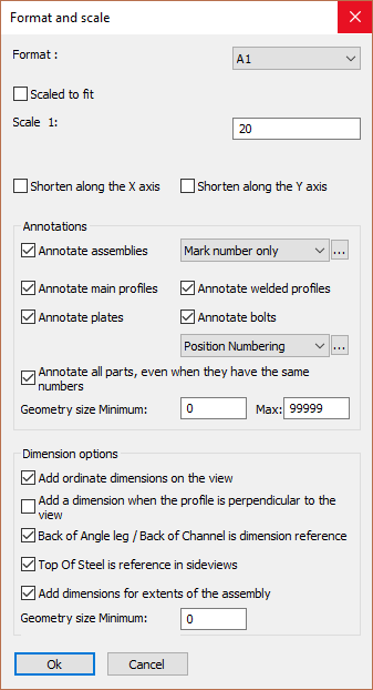
For the purposes of this exercise, select plan views for: World (WCS) and Top. In the following Format and scale dialog, select the drawing format to A1 and the scale to 1:20.
Finally activate all the Annotations in the Format and scale checkboxes and press Ok
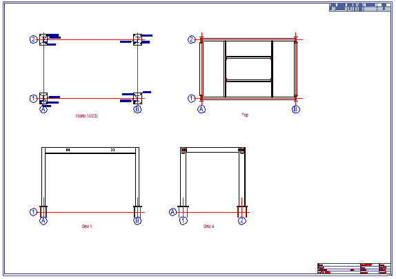
As we are placing multiple plan views, follow the command line prompt and Select the location where the view is to be drawn - World - indicate a place on the drawing sheet and press the left mouse button to confirm. Following the command line prompt again, indicate a position to place the view Top. Don't worry if the positions are a bit random at this stage - just try to ensure that the views don't overlap on the drawing.
Next we'll place some elevations on the drawing - Repeat the Add new plan views process and select Grid 1 - follow the command line prompt and place it on the drawing sheet. Repeat this process for Grid A.
At this stage, it's good practice to align the views so that they project along common lines - in other words, align the plans horizontally, with the elevations or sections aligned with the plans. This is done using the built-in CAD move / copy commands. See example below.
In Europe (and most of the world) Third angle orthographic projection is used whereby the plan views are placed above the elevations, in the US, First angle projection is used whereby the plans and elevations are switched.
Manually editing the drawing
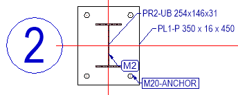
Often it's necessary to manually edit parts of the drawing - usually to make things clearer and easier to read, an example of which, in this instance, are the text and labels around the base plates.
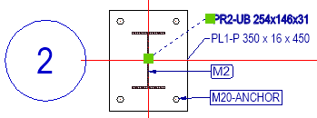
To move text and labels, indicate the text or label to be moved with the left mouse button, and holding the text grips, relocate it.
To change the appearance of the object (The grid line notation in this case) double click the item and modify its Properties.
Do not modify the Values!
|
|
Before Editing |
After Editing |
Adding Dimensions
Parabuild has a full range of dimension commands derived from the regular CAD properties. The options for dimensioning are full explained in Dimensioning.
Adding Levels Notation
Levels notation may be added to Elevations and Sections using the Levels command
The options available for editing the Drawing frame, Title Block, Bill of Materials, and General notes templates are as noted for Position and Assembly Sheets
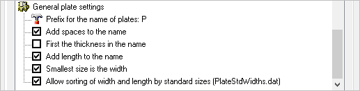
General Plate Settings
Parabuild has the facility to change the appearance of the plate notation on the drawing, where you can add spaces to the name, alter the order in which the plates are noted etc. This facility is available from Global Settings
Bills of Material / Bolt Lists
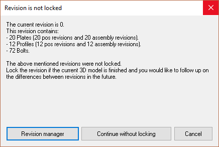
To generate all bills, open the Sheets manager from the Main - Output menu. Press the Generate button to open the drop-down options, and select Generate Bills you will be prompted to update the revision from the Revision manager or Continue without locking. In this case Continue
The Bills will be automatically generated and then immediately opened in Excel, Open Office or the Parabuild spreadsheet. The format used depends on the output setting in the bill's Settings. The file will be stored in the same folder as the 3D DWG files.
Settings for bills of material
There are numerous option available for the presentation of bills of material contained in Document generation Settings / Bills of Material here you can create, save, and load Bills.
Bills can be customized to suit by accessing the Bills of material / Formatting options, where you can edit the Bill type and format, You can also adjust the column type, column order, and sub-total columns. You can also add filters to aid in the sorting.
This completes the first exercise, at this point we have produced a working model of a simple post and beam structure using both Model Lines and Parabuild's Context Modeler. In preparing this model, we have added base plates and connections, providing and introduction into the use of Parabuild's macro edit dialog system.
We have produced Detail and Assembly drawings, together with Bills-of-material, Bolt-Lists, and General Arrangement drawings, each of which were automatically derived from the model.
We have also seen how we can modify and customize the drawing sheets and bills of materials to suit requirements in order to present accurate and professional documents.
At this point, you should repeat these exercises using different profiles and section sizes, use different connection options, and adjust the settings for dimensions and bills.
Mastery of this simple exercise will provide you with an in-depth insight into the workings of Parabuild so that you may confidently approach the next steps.