DXF Settings
The DXF settings explained in this topic can be accessed from the Document generation Settings : CNC tab : DXFs tab
Scope of these settings
This topic explains the Dxf settings of a single DXF configuration.
However the settings for weld contours and match lines are general settings that apply to all CNC files, not just the Dxf files.
You can read more about these general contour settings in these 2 topics :
- The Check CNC contours when numbering parts settings influence the numbering of parts, so that the CNC filenames become shorter and simpler.
- The CNC contour and matchline settings allow you to enable lines or punch marks in the CNC files automatically at the locations where parts need to be welded. This will greatly reduce time spent and mistakes made in the workshop.
The DXF Settings dialog allows you to change the following settings which are explained below :
The General tab
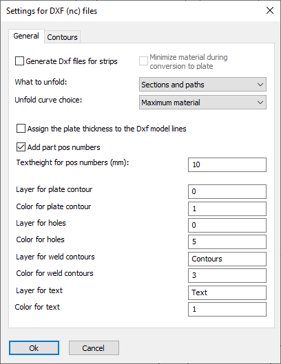
Generate Dxf files for strips - When this option is enabled Parabuild will convert strips into regular Parabuild 2,5D plates. Then the DXF file of this plate can be generated. The conversion is temporary so this will not change the part in the 3D model and it will not affect the number of the part.
The conversion itself may cause a loss of 3D complexity of the strip, and that is what the Minimize material option is for.
You can learn more about this conversion in the Convert Strip or Plate topic.
What to unfold - You can optionally enable unfolding of profiles or strips just before generating the Dxf file here.
Only the parts that have unfolding enabled will be unfolded. There are several ways to enable unfolding on a part and this is explained in the topic
Enabling unfolding for Dxf/Dstv and shop drawings.
This option allows you to choose what should be unfolded : the section of the profile or the axis of the profile, or both.
Unfold curve choice - When unfolding, the bends are not only neutralized from the part, but also the part is flattened to a 2D plate.
As a consequence, there are multiple ways in which the flattening can be done.
First, Parabuild will retrieve the neutral axis and this can be configured in the Advanced properties of the part, in the section table of the profile, or with a k-factor table in the global settings. The k-factor will be retrieved from these 3 sources in this order. If the k-factor could not be retrieved from any of the sources for the part then the default k-factor of 0.5 will be used.
Then the unfold curve choice is also needed for the unfold.
The option on this dialog will be used, but if it is set to <Not set> then it will be retrieved from the section table or from the Advanced properties in that order.
The actual meaning of these 4 curve choices are explained in the section table topic.
For more general information about unfolding see the Unfolding topic.
Assign the plate thickness to the Dxf model lines - When active, the thickness of the plate will be assigned to the model lines in the dxf files. This creates a semi 3D model and the machine can know the required thickness of the plate this way. Some machines can't read the dxf file when this option is active.
Add part position numbers - The position number of the plate will be added as text to the DXF file so that the machine can engrave it on the plate.
Text height for position numbers - Set the text height for position numbers on the part.
* The remaining options allow you to set the layers and colors of the different line types and texts.
The contours tab has the following options :
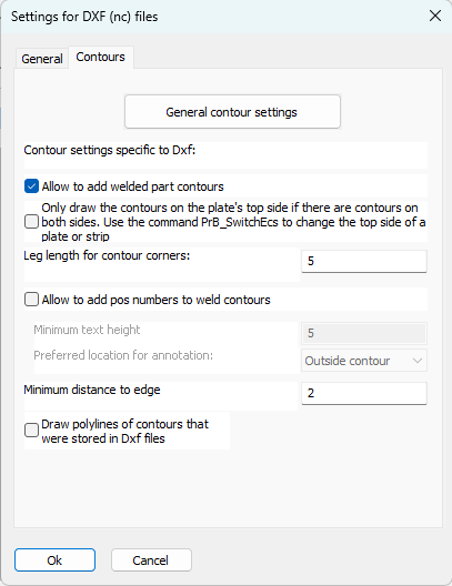
General contour settings - For more information about the options behind this button, see the CNC contour and matchline settings topic.
Also related to the contours and match lines are the Check CNC contours when numbering parts settings.
Only draw the contours on the plate's top side if there are contours on both sides - Enable this to manually influence the contour side choice for plates.
When this option is disabled then Parabuild will automatically choose the best side of the plate. When multiple parts are attached to a side then that side will be chosen. When the amount of parts is the same on both sides, then it will choose the side with the longest contours.
When this option is enabled then Parabuild will always choose the top side of the plate when both the top and bottom sides have contours.
You can use the command Switch Profile/Plate triangle direction to switch the top and bottom side of a plate or strip.
Note that for plates the long triangle is not necessarily the X axis of the plate. This triangle's orientation can be changed in the Global settings or even be replaced by a small coordinate system called Detailed Ucs icon.
Allow to add welded part contours - When active, the weld contour options become visible. Contours will be added as per the CNC contour settings.
Leg length for contour corners - This is the length of the 2 legs whenever a contour corner is drawn
Allow to add position numbers to weld contours - Wen active, position numbers will be added to weld contours as per the CNC contour settings.
Minimum text height - Set the minimum text height for the position numbers of the contour. Parabuild will deviate from the standard text height in order to fit the text in places without much room, but will not use a text height below this value.
Preferred location for annotation : Normal behavior is to place this annotation outside of the contour. You can choose inside of the contour, but if the text is too large to fit in the contour then it will be placed outside of the contour.
Minimum distance to edge - Set the minimum distance that should be kept between the text and the edge of the plate
Draw polylines of contours that were stored in Dxf files - When you enable this then Parabuild will draw in the 3D model the contour lines and text that it has put inside the Dxf files. These lines and texts are put on the PrB_Contours layer.
All of the contours and texts are drawn exactly on top of the faces of the 3D parts where the Dxf files have received that same contour or text.
This is a practical way for you to check whether your contour settings are adding the contours that you need.
These text fields have no other purpose than this checking and they will not be used the next time that CNC files are generated.
If you generate CNC several times with this option enabled then it will draw these contours on top of each other.
This may be annoying but it does no harm either.
To clearly see these contour lines you should switch the visual style to 2D wireframe, 3D wireframe or X-Ray.
Not all of the parts in your 3D model will get these contours. Only the reference parts that Parabuild has chosen for CNC generation will get the contours and text fields.