Pipe Wraparound Settings
This topic explains the settings of the Generate WrapAround for Pipes.
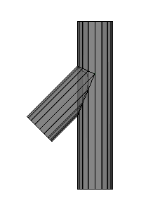
A wraparound is a foldout of the pipe on a flat 2D surface which could look like this :
|
|
|
|
Example of a 3D model |
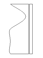
The resulting wraparound of the short pipe generated by this tool, including shortening which can be disabled |
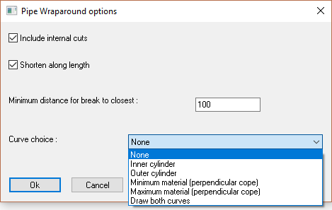
The different options in the dialog are explored below :
Include internal cuts - If disabled, only the cuts at the endings of the pipe would be processed.
Shorten along length - If enabled, the wraparound will be shortened on the straight lines, saving space in the dxf file.
Minimum distance for break to closest - This relates to the shortening : It is the minimum distance that should be kept between the shortening line and the closest curves that can't be shortened.
Curve choice - Generating the wraparound of the 3D model will cause a loss of information.
We are after all exporting just 1 layer of the pipe, whereas the actual pipe in 3D consists of many layers that could be exported.
These are the available options for the curve choice :
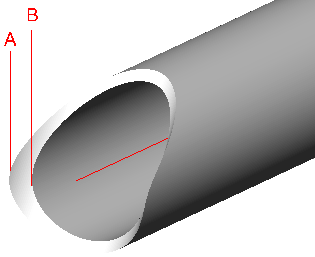
- Inner cylinder - The curves of the inner cylinder are used (cylinder B in the illustration)
- Outer cylinder - The curves of the outer cylinder are used (cylinder A in the illustration)
- Minimum material - Parabuild will choose the inner or outer automatically depending on which would cut the most amount of material away. Perpendicular cutting is assumed.
- Maximum material - Parabuild will choose the inner or outer automatically depending on which would cut the least amount of material away. Perpendicular cutting is assumed.
- Draw both curves - This option will draw both the inner and the outer curves.