Global settings
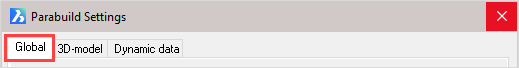
The global settings are divided into the following categories:
- Drawing parabuild elements
- Languages
- Standard tolerances for cutting
- Distances
- Standards of the position numbers of plates
- Standards of the position numbers of members
- Standards of the position numbers of structures
- Standards of assembly numbers
- Global settings
- Standard values for newly drawn members and plates
- General plate settings
The buttons at the bottom of the dialog are referenced here:
- Library Localization
- Bolt Parts database
- Bolt Assemblies
- Variables of Macros
- Material / Finishing
- Threaded Holes
- DSTV WeldPoints
- Clash Control
- Object Filters
- Structural types
- CNC contour settings
Drawing Parabuild Elements
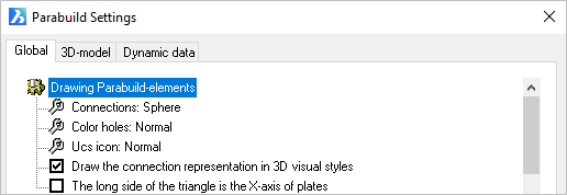
Connections: Refers to the macro indicator - Options = Not / Sphere / Triangle
Color Holes: Hole color - Options = Normal / Red
UCS icon: This refers to the coordinates system of plates and profiles. Options = Normal, which draws a triangle at the origin / Detail, which draws a UCS icon at the origin.
Draw the connection representation in 3D visual styles: A switch, which when checked will show the macro spheres when one of the 3D visual styles are active. When unchecked all spheres will be hidden.
The long side of the triangle is the X axis of the plates: The origin triangle direction may be switched from the Y axis (checkbox UnChecked) to the X axis (Checked). This option will only come into effect when the UCS icon is set to Normal
Languages
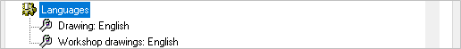
The language option for Drawing refers to the language of the user interface in Parabuild. That means all the dialog boxes, command line prompts and toolbars.
The language option for Workshop drawings refers to the language of the automatically generated workshop drawings and GA drawings only. More specifically the title block and Bill of Material on these drawings.
The available languages include:
- English
- Dutch
- French
- German
- Korean
- Traditional Chinese
Distances
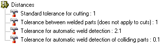
Standard tolerance for cutting: Commands for adding cuts to parts will follow this default value. Default value = 1 mm.
Tolerance between welded parts (does not apply to cuts): The distance (gap) that should be generally applied between welded parts. This applies to all welded parts except in case a cut is touching one of the parts. In case of a cut, the above tolerance counts.
Tolerance for automatic weld detection: This tolerance is used by the Workshop Drawings generation command, and by the DSTV and DXF export commands. When parts are not touching but within this tolerance, then Parabuild will assume that the parts are touching and need to be welded. The touching status will determine whether the welded part will get certain dimension on the shop drawing or CNC contours or matchlines in the CNC files.
Tolerance for automatic weld detection of colliding parts: This tolerance is used by the Workshop Drawings generation command, and by the DSTV and DXF export commands. When parts are not touching but colliding with each other but within this tolerance, then Parabuild will assume that the parts are touching and need to be welded. The touching status will determine whether the welded part will get certain dimension on the shop drawing or CNC contours or matchlines in the CNC files.
Standards for the position numbers of plates
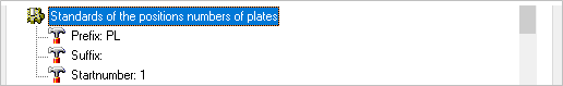
Prefix: Is the prefix given to plate numbers i.e. PL 1 - this may be edited to suit
Suffix: Is the suffix given to plate numbers i.e. PL 1 01 - this is optional
Start number: Is the first number given to the plate i.e. PL500. This number will be automatically incremented if the given start number is already occupied.
Standards for the position numbers of members
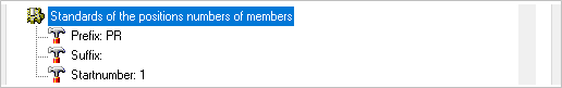
Prefix: Is the prefix given to member numbers i.e. PR 1 - this may be edited to suit
Suffix: Is the suffix given to member numbers i.e. PR 1 01 - this is optional
Start number: Is the first number given to the member i.e. PR500. This number will be automatically incremented if the given start number is already occupied.
Standards for the position numbers of structures
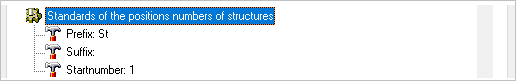
Prefix: Is the prefix given to structure numbers i.e. ST 1 - this may be edited to suit
Suffix: Is the suffix given to structure numbers i.e. ST 1 01 - this is optional
Start number: Is the first number given to the structure i.e. ST500. This number will be automatically incremented if the given start number is already occupied.
Standards of the assembly numbers
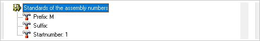
Prefix: Is the prefix given to assembly numbers i.e. M 1 - this may be edited to suit
Suffix: Is the suffix given to assembly numbers i.e. M 1 01 - this is optional
Start number: Is the first number given to the assembly i.e. M500. This number will be automatically incremented if the given start number is already occupied.
Global Settings
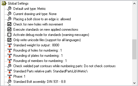
Default unit type: Use None if you want to work in both Metric and Imperial projects. Choosing Metric will cause Parabuild to assume Metric in drawings with conflicting units variables. The same applies to the Inches option. Options = None / Metric / Inches
Current drawing unit type: Change this option only when Parabuild has assumed the wrong units for the current 3D drawing. Options = None / Metric / Inches
The following variables are used by Parabuild to conclude whether a dwg file is Metric or Imperial :
Variable name |
Variable value |
Measurement |
0 for Imperial 1 for Metric |
LUnits |
2 for decimal metric 3 or higher for imperial |
InsUnits |
1 for Imperial 4 for millimeters |
The setting Current drawing unit type in this dialog box will be set to what could be derived from these 3 variables. You can change the setting in this dialog to correct it if needed.
AutoCAD and BricsCAD also have the following variables that may interest you especially when working with Imperial units:
Variable name |
Variable value |
Dimzin |
Controls the suppression of zeros in the primary unit value in dimensions. 0-7 for Imperial 8 for Metric |
Dimtzin |
Controls the suppression of zeros in tolerance values in dimensions. 0-3 for Imperial 4, 8 and 12 for Metric |
DimFrac |
Sets the fraction format when DIMLUNIT is set to 4 (Architectural) or 5 (Fractional). 0 : Horizontal stacking 1 : Diagonal stacking 2 : Not stacked (for example : 1/2) |
DIMTFac |
Scale factor for fractions |
DimLUnit |
Sets units for all dimension types except Angular. 1 : Scientific |
DimPost |
Specifies a text prefix or suffix (or both) to the dimension measurement. |
luprec |
Sets the display precision for linear units and coordinates. |
unitmode |
Controls the display format for units. 0 : Displays fractional, feet-and-inches, and surveyor's angles in "report" format using spaces as delimiters 1 : Displays fractional, feet-and-inches, and surveyor's angles in "input" format without including spaces and, in some cases, substituting dashes for spaces |
InsunitsDefSource / InsUnitsDefTarget |
These are only used when the source or target drawings of an insert operation don't have the InsUnits variable set |
Placing bolt close to an edge: Options = Not allowed / Allowed
(The minimum distance between a bolt and the edge of a beam or plate can be set in the Clash Control dialog)
Check for new holes with movement: Options = Off / On
(When a bolt is moved, the corresponding holes are moved with it. You can switch this off)
Execute standards on new applied connections: Options = On / Off (Refer to Standards for Connections)
Activate debug mode for standards (Warning messages): Options - On / Off
Only write Unicode files (Support for all languages): Options - On / Off
Standard weight for output: This value is the default weight that Parabuild should assume for objects that have no material assigned. The default value is set at 8000 kg/m³ - which is the approximate value for 1m3 of steel (7860 kg/m³).
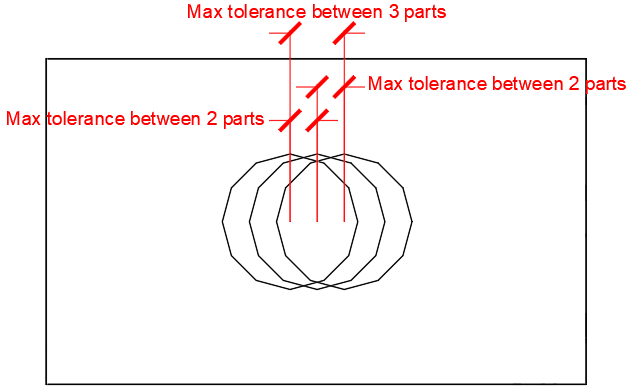
Rounding of holes for numbering: This is the tolerance that Parabuild should use when searching for identical parts and assigning numbers to them.
In practice, Parabuild will assume half of this tolerance when comparing 2 parts. This means that the total maximum difference between 3 parts will be the full tolerance.
The below illustration shows the difference between the tolerance of 2 parts and the total tolerance of 3 parts or more.
It shows 3 plates on top of each other, but with slightly offset hole positions.
Rounding of plates for numbering: Same as above, but this refers to the tolerance of plate edges for number assignment.
Rounding of members for numbering: Same as above, but this refers to the tolerance of member edges and cuts for number assignment.
Check welded part contours while numbering parts - This option is explained in detail in the Check contours when numbering parts topic.
Standard parts relative path: This value should point to a folder inside the Parabuild library (the full path is by default c:\Parabuild\Pb_Lib\StandardPartsLib\Metric\).
This tool is meant to create library drawings that contain pre-made “off the shelf” parts.
You will assign recognizable part numbers to the "off the shelf" parts so that the persons in the shop know which part to take. Typically there is no shop drawing needed for these parts.
This is how it works :
During the numbering stage, Parabuild will open all the 3D drawing files in this folder, and it stores all of the plates, profiles and structures in those files into memory.
Then when it encounters a part in your current drawing with the same geometry as in the standard parts, then the part number will be inherited from the part that was stored in the standard parts file.
Also a limited number of properties such as Skip shop drawing generation will be inherited.
Phase: Sets the phase that all newly drawn objects should receive.
Standard bolt assembly: The default bolt assembly that connections and bolt tools should use by default. (See Bolt Assemblies)
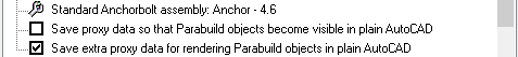
Standard anchor bolt assembly: The default bolt assembly that anchor plate macros should use by default. (See Bolt Assemblies)
Save proxy data so that Parabuild objects become visible in plain AutoCAD/BricsCAD: This option allows the 'Proxy' details of a 3D-drawing to be saved. Parabuild creates its own objects (profiles, plates, bolts ...) which means that without Parabuild, AutoCAD will not recognize these objects and therefore will not display the profiles. This is solved by the 'proxy' details, details on the appearance of the objects, which is saved within the drawing. One disadvantage of this is that the drawing becomes 2 to 3 times larger. However, this does not result in any great delay when opening or editing the drawing, as these details are not actively used, and is therefore not loaded into memory when working with Parabuild. Remember that when this option is turned on within an existing drawing and then saved normally, the details are not yet saved. This can be solved by either setting the variable 'ISAVEPERCENT' to 0, or by saving the drawing under another name.
One final requirement is that the proxy details on the computer without Parabuild is set to display. This can be set up in AutoCAD as follows: Tools > Options > Open And Save > Proxy Images for custom objects should be set to Show proxy graphics.
Save extra proxy data for rendering Parabuild objects in plain AutoCAD/BricsCAD: this is a sub-set of the previous option. This will add additional proxy data for rendering of faces with 3D objects. Note that this option will not work independently as the edges are still needed to determine the faces. Therefore, both check boxes must be active if you want the rendering data to be written to file.
Standard values for newly drawn beams and plates
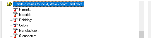
Remark: Here you may enter a standard Remark for newly drawn parts
Material: Here you may enter a standard material for newly drawn parts
Finishing: Here you may enter a standard Finishing for newly drawn parts
Color: Here you may enter a standard Color for newly drawn parts
Manufacturer: Here you may enter a nominated Manufacturer for newly drawn parts
Group name: This property is not actively used by Parabuild, so it can be considered a free to be used "User property".
General plate settings
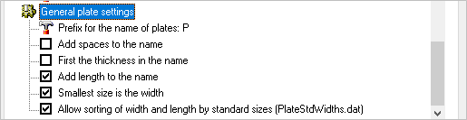
Prefix for the name of plates: The default value is PL - this may be changed to suit preference (i.e. PL8x100)
Add spaces to the name: Will add spaces between the characters (i.e. PL 8 x 100)
First the thickness in the name: Will place the plate thickness before the plate size (PL8x100 vs PL100x8)
Add length to the name: Will add the plate length to the plate name (i.e. PL8x100x190)
Smallest size is the width: Will assume the smallest size is the plate width (i.e. PL8x135x200 vs PL8x200x135)
Allow sorting of width and length by standard sizes (PlateStdWidths.dat): If enabled, Parabuild will use this file to determine what the standard plate widths are : c:\Parabuild\Pb_Lib\PlateStdWidths.dat.