Railing
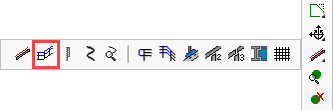
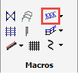
Command - PrB_Railing
This command can draw railing segments on top of lines or profile edges. It will also connect these railing segments wherever possible.
After activating this command the Insert a railing dialog will appear, giving you the following options:
- Railing: This option will draw both handrail / knee-rail complete with a flexible amount of stanchions. By default it has a minimum of 2 stanchions. The number of stanchions will grow depending on the railing segment's length.
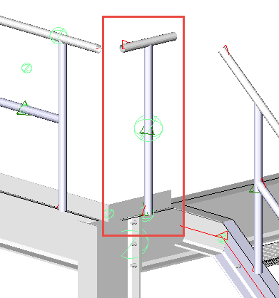
- Railing 1 post: This option will draw the Hand and Knee-rail only with just 1 vertical stanchions. This option would be used when the railing segment is so small that only 1 stanchion is needed. An example of such situation :
|
|
The first result after drawing the railing segment with just 1 post |
The end result after using the Railing intersection connections on it |
- Railing - no posts: This option will draw the Hand and Knee-rail only without vertical stanchions. This option would be used when the railing segment is so small that no stanchions are needed. An example of such situation :
|
|
The first result after drawing the railing segment without posts |
The end result after using the Railing end connections and Railing intersection connections on it |
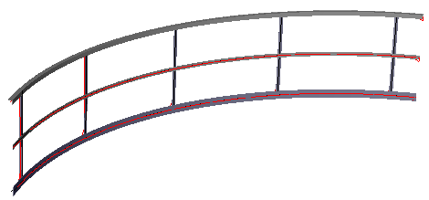
- Curved railing - A curved railing can be drawn by selecting an arc or an edged of a curved profile.
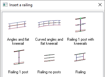
Select the desired option and press OK - then select the profile or line on which to place the railing
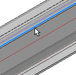
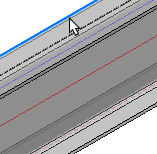
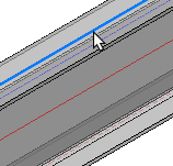
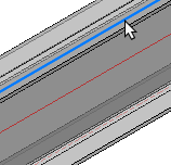
Here, it's important to note, that the selected edge of the beam will determine the placement, which may be either of the top edges, the center of the beam, or a user drawn line.
Note that the selected edge will become the center of the handrail. This location can still be offset afterwards.
The handrail may be edited at any time by means of the Review Macro command.
|
|
|
|
Near Side Edge |
Far Side Edge |
Center |
User defined line |
Next you will be prompted to select a geometry to shorten the railing
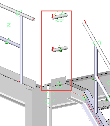
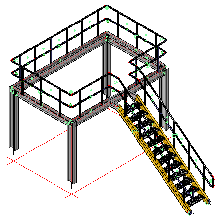
Pressing <Enter> will draw the handrail the full length of the selected member or line, disregarding any incoming stairs or platforms (See Fig. 1)
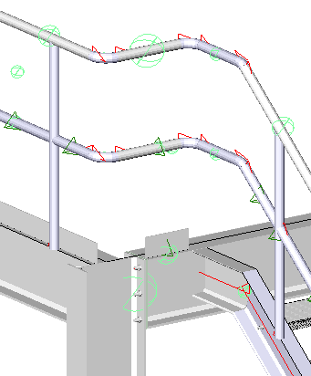
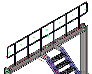
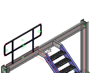
Alternatively, you may select an incoming beam or stair stringer to shorten the railing (See Fig. 2)
|
|
Pressing <Enter> will draw the handrail the full length of the selected member or line |
Indicating a geometry to shorten the railing - in this case - the inside face of the incoming stair stringer |
Chaining the handrail segments
After drawing the first handrail segment - the prompts will repeat allowing you to continue to trace the handrail route. Parabuild will automatically join the handrail segments together. To enable this sequential operation to work at its best, the handrail segments should be selected contiguously.
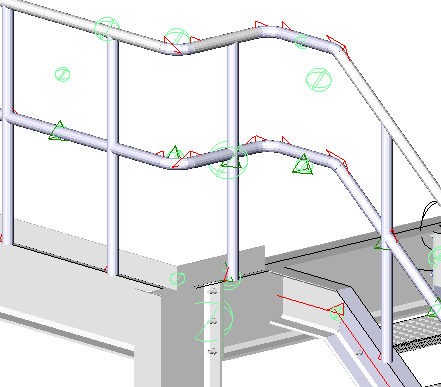
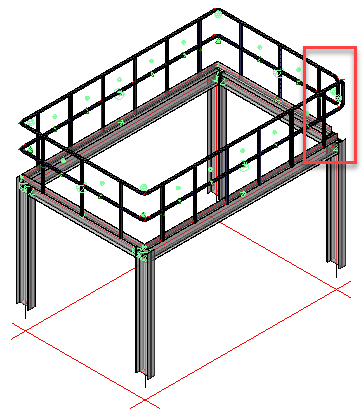
Parabuild will automatically insert a closure at non-contiguous joints. In the example illustrated below, the handrail was begun and ended at the stair - in which case the closures at the bottom of the stair are appropriate.
If the handrail is placed around a platform with no shortened segments, the closures will still be placed at the beginning and end of the chained handrail segments. To rectify this, delete the closure segments using the Delete macro command and activate the Railing intersection connections command and select the handrail stanchions - Press <Enter> and the returns will be automatically drawn.
Editing the Handrail Dialog
As the handrail is drawn, the handrail edit dialog will appear. This dialog has 3 tabs: Railing / Toe Plate / Connectors
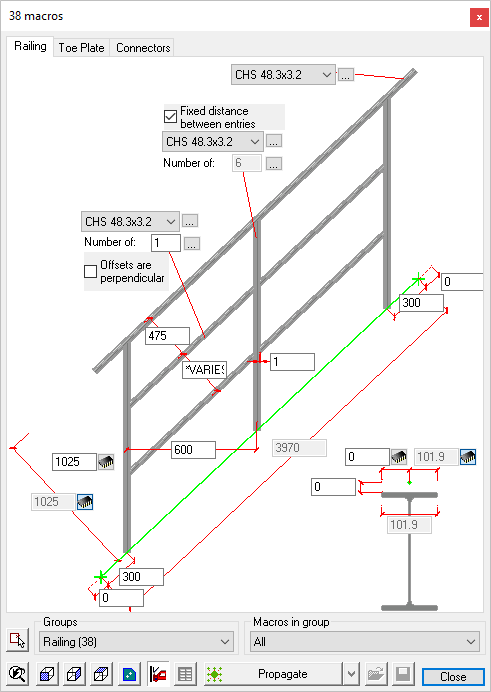
Railing:
Here, you may edit the handrail, knee rail, and stanchion section sizes. By default they are drawn as standard Circular Hollow Sections - by activating the drop down options menus adjacent to the default size, you may select another size.
Hitting the button to the right will open the Profile placement dialog where you are able to select a section from another group. (Be careful when doing this as it may require significant editing of the various handrail joints and connections)
It is also possible to edit the stanchion and handrail spacing.
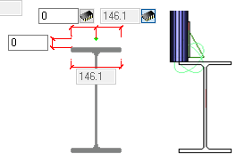
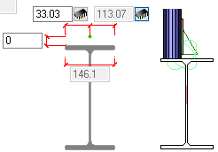
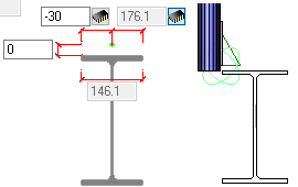
Placing the handrail relative to the beam or stringer can be done by revising the dimensions at the bottom/right of the dialog
|
|
|
Handrail located on edge of beam |
Handrail located on beam flange For base-plate mounting |
Handrail located to clear beam flange For side-plate mounting |
Toe Plate:
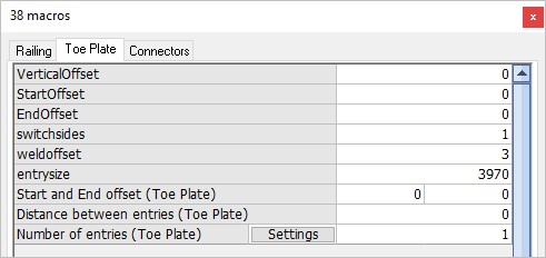
The options for editing the Toe Plate or Kick Plate include:
Vertical offset - the distance between the bottom of the toe plate and top of steel
Start offset - The horizontal offset at the beginning of the toe plate
End Offset - The horizontal offset at the end of the toe plate
Switch sides - Is a boolean variable, a value of 0 will place the toe plate on the inside of the handrail stanchion, while a value of 1 will place it on the outside
Weld offset - refers to the weld gap between the stanchion and the toe plate, the default setting is 3 mm
Connectors:
The Connectors tab contains 2 options:
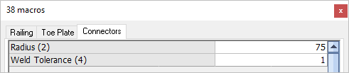
Radius - Here you may edit the radius of the bends
Weld Tolerance - Here you may edit the weld gap between the bends and the horizontal rails.