Propagate
With this new tool you can automatically distribute a connection to other profiles in the drawing with the click of a button.
The distribution is based on geometric recognition. If the base profiles are of the same type and have a similar position with respect to each other, the connection is automatically copied. This will save you a lot of time when the same types of connections are used often.
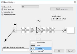
Weld specifications
With this new command you can easily draw weld symbols on the workshop drawings.
The configuration of the symbol was entirely done with visual aids, resulting in an easy to use tool.
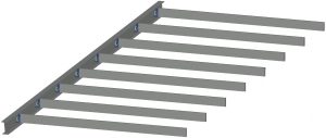
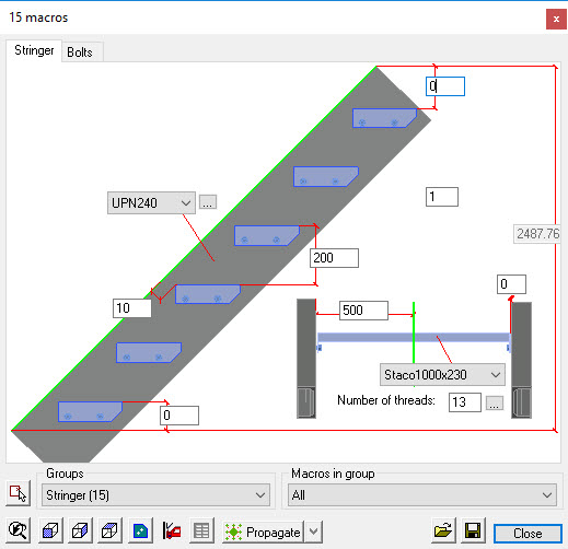
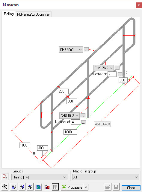
Stairs and handrails
The tools for drawing industrial stairs and railings has been completely renewed. The stairs and railings are now fully built up with the aid of macros. Thanks to these macros you can still adjust the parts after they are drawn via the macro window.
A stair can be drawn based on a line, or between 2 beams. A railing can be drawn on top of a profile or a line.
A series of connections were also added to connect the handrails and the stair stringers.
2 new cage ladders were also added: A cage ladder with a larger ring at the bottom, and a cage ladder according to the PIP STF05501 standard.
This is only the beginning of the changes to stairs in Parabuild.
Numbering
- When you change the 3D model, it is now much more likely that Parabuild will retain the numbers of the parts and assemblies. The previous number will be reused unless another part or assembly with different sizes already uses this number.
- It is now also possible to assign a preferred number to parts and assemblies. Parabuild then gives priority to the part / assembly when assigning this number. This preferred number is only applied when it does not lead to parts / assemblies with different dimensions having the same number.
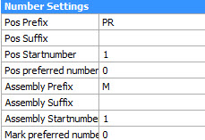
- A new button was created that copies all current numbers to the preferred numbers. This ensures that parts / assemblies retain their number as much as possible after a change of the 3D model. When after a revision a part / assembly number would split up into different numbers, then by a change to the prefix or suffix it can be ensured that they all still refer to the original number.
- For example: There are 5 pieces of the assembly M7 and they have 7 as the preferred number. After a revision some components change and they do not have the same geometry anymore, so they get a different number. For all of them the preferred number is still at ‘7’ so by using a new suffix the preferred number can be used again and the numbers become for example ‘M7a’, ‘M7b’, …
BIM integration with BricsCAD
When a generic solids model is opened in BricsCAD, BricsCAD has the ability to recognize these solids as linear profiles: ‘Bimify’. After BricsCAD has applied BIM information to the profiles there is no further intervention needed to convert the linear Solids to Parabuild profiles.
The conversion will be done automatically when using the context modeler on the solids or when attempting to connect the solids.
When you perform an Ifc export using the BricsCAD command, then all BricsCAD objects such as BIM elements and 3D Solids are now exported together with all Parabuild objects in the same Ifc file.
These functions will only work in combination with the BricsCAD V18 BIM module.
![]() Watch our presentation of these new features at the Bricsys Conference 2017
Watch our presentation of these new features at the Bricsys Conference 2017
Manipulate elements without using UCS
With this new function you can perform a series of actions on one or more elements.
The purpose of this is that you can move or rotate the elements in a certain direction without having to change the UCS first. This is especially interesting if the movement you need to perform is not according to the World X, Y or Z axis.
You use a plane or line of another element as a basis for the movement or rotation.
These are the actions you can perform:
- Set the distance between the elements
- Move a certain distance
- Make Parallel / Perpendicular
- Rotate the element at a certain angle
Performance
Extra attention was paid to the performance in Parabuild.
For example, calculating macros is much faster. The opening of large drawings has also been greatly accelerated.
The drawing of holes in 3D visual styles was also improved, which results in a high performance improvement when using these visual styles.
DXF
Writing of DXF files for plates was greatly improved. The welding contours are now correctly trimmed, and the texts will no longer be drawn over these contours.
The Dxf files can now be sorted automatically into a folder per thickness.
Sheet metal unfold
In the properties panel you can now directly request the unfolding of a folded parted. This command works on strips as well as on profiles with 2 different cross-sections.
To use this function, you will need the BricsCAD Sheet Metal module.
Generating STEP files
In the properties panel you can now directly generate a Step file from a profile, plate or volume.
Step files can often be read by CNC machines that process pipes.
To use this function, you will need the BricsCAD Communicator module.
Parabuild is now compatible with BricsCAD V18
And much more…
- All hole and cut position dimensions of the main part can now also be drawn automatically on the assembly drawings.
- It is now possible to import and export files using the CIS/2 standard (CIM Steel Integration Standard). The file exchange was tested and works with Smart Plant 3D v2016 and with CADWorx Structure 2018.
- Parabuild now includes 2 ribbon tabs and a menu bar that give you access to all the Parabuild functions.

- Double-clicking an object will now open the relevant dialog box for editing that object.
If you double-click a macro, a bolt or a plate, then the relevant macro dialog box will be opened.
If the object is not a part of a macro, then the properties window will be opened. - The following connections were added: base plates with square holes, base plates with plates as washers, welded joints, more purlin connections, rectangular hole reinforced with plates, and gusset plates for bracings of UPN profiles.
- The tapped holes were improved. An old mistake where the tapped holes are larger than the bolt was eliminated. The configuration table of the diameters to be drilled and tapped was adjusted to follow this change.
- Many properties were added for views and cameras
- New command: Prb_GetCenterOfGravity. This command draws the center of gravity of a selection of elements.
The full list of changes and the location of the new features and options can be found in the release notes.