We are proud to announce a new release of Parabuild that focuses on improved automation document generation and expanded bolt features
These are the most important new features that were made available in this update:
Much more flexibility for the settings of workshop drawings, CNC files and parts lists
The settings of workshop drawings can now be made dependent on the type or properties of each part or assembly.
Both simple conditions such as the structural type and complex filtering that combine different properties are possible, using the existing Parabuild filter system.
Some application examples for this new option are:
- To provide structural columns different settings for their dimensions on the assembly drawing
- Configure railings to use other side views as well as other dimensions
- Configure simple parts or assemblies with just 1 view
- Group parts or assemblies of the same type on the same pages, or on consecutive pages
- Based on size, type or other properties, decide what type of CNC file should be automatically generated (e.g. DSTV and/or DXF), and with what settings, such as whether or not to allow outline scribing and/or part numbers.
GA view presets and multiple views per camera
These tools allow the drafter to very quickly add general arrangement views, section views and detail views on the GA sheets with automatic annotation placement done automatically.
Pre-configuring view settings allows some views to have different annotations or appearance than other views, such as disabled or enabled hidden lines.
A single camera in the model can now be used as a basis for multiple views that each have a different view point, and can have different appearance and annotations. Upon creation, each view can be placed one after the other with a single click for each view.
Transfer colors and line types from 3D to 2D views
In this update, the user gains more control over colors and line types of the views on shop drawings and general arrangement drawings. This way they can be configured individually per saved “representation style”. It will also be possible to transfer the colors and layers of 3D objects to the 2D views.
Furthermore, the representation of the objects in a view can be configured based on object filters, to present objects differently depending on the purpose of the 2D drawing – for example to make certain types of elements more or less striking. This can be used, for example, to make an underlayer or an existing construction light gray on the surface.
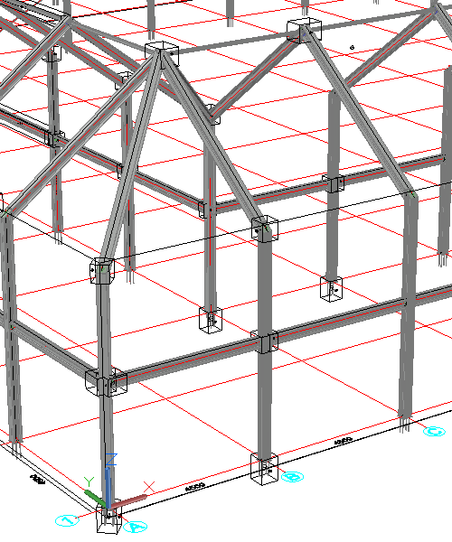
Automatic creation of cameras in the model
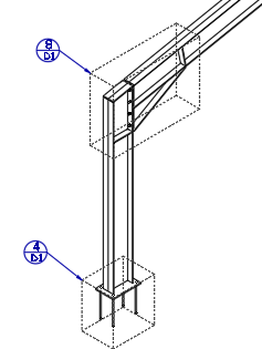
A new tool was added for automatically creating cameras in the model based on macro spheres or a manual selection of parts. Either select multiple connections/macro’s and a box camera will automatically be created for each selected macro, or select a set of geometries and a camera will be created that fits the selection. This is especially useful for creating connection detail views.
If the chosen primary view direction was not ideal, a quick grip stretch operation is enough to change the viewing direction.
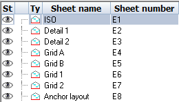 Sheet and View numbers
Sheets and views can now be automatically numbered based on a template string that allows you to choose the prefix, suffix and start number.
Numbers are assigned sequentially based on time of creation, but can be updated later and once changed Parabuild will renumber other views/sheets to avoid conflicts when needed.
Further, a new view renumbering command allows to quickly renumber all views on a sheet sequentially while still respecting their number template.
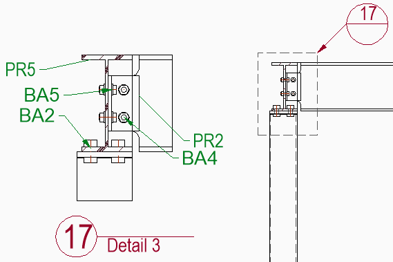
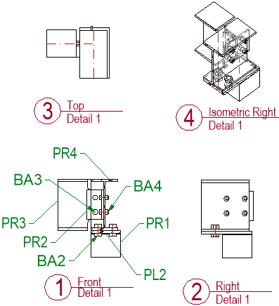
View symbols and callouts
The Parabuild annotations now support view symbols and callout symbols. View symbols will be automatically placed under views when configured that way in drawing settings and annotation styles.
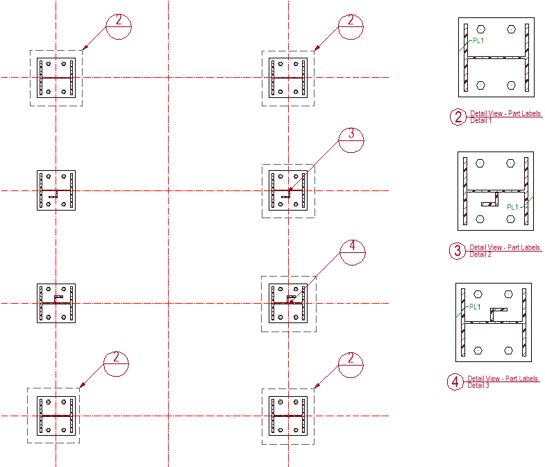
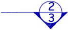
Detail and section view callouts that refer to other views can be created using the callout command on cameras contained in a view. When adding a new detail on an existing view a callout will be drawn automatically. By default the callout symbol will contain the view number on the top half of the circle, and if the called out view is on a different sheet, the bottom half will contain the sheet number.
View symbols and callouts will update when view numbers or sheet numbers change.
|
|
|
|
View symbol example |
Section view symbol example |
|
|
|
|
Detail callout example |
Section callout example |


 Cameras inside views
Cameras on the model can be automatically inserted into main views during creation, or they can be pulled in while editing the view.
It is also possible to add so-called referring callout cameras to a view, this way a single view can be linked to multiple callouts on multiple other views.
It is possible to manage all the cameras of a view in the new camera management dialog.
The drafter can do the following changes :
- Enable or disable a camera for printing
- Show all cameras even those that will not be printed
- Add a referring callout camera to the view. This can be any camera anywhere in the model
- Change the view to which a camera is referring to. This can be useful as a camera can be linked to several views.
In aligned views box-based detail cameras are shown using a rectangle. Views that are not aligned with the detail camera, such as on isometric views, can now also show the detail camera as a 3D box to support callouts.
Object appearance overrides
The appearance of objects on the view can be overridden on a per-object level. Filters can be created to target objects based on layer, material, structural type, and other properties and geometric characteristics and assign those objects a certain color, linetype, transparency, or have them be skip entirely in a specific view.
Example usages of this are to give an underlayer a grey color, making concrete slabs transparent so the parts behind them are still fully visible, or skipping certain part types from section views to unclutter them.
Improved hatches on views
Hatch patterns can be configured based on material type or any other property of the parts.
Hatch patterns will automatically be drawn for sectioned objects on section views and on isometric views that were clipped.
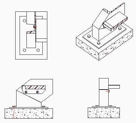
Automatic section views on assembly drawings
Section views can be automatically created for assembly drawings, based on object filters to identify which parts should get which type of section view.
Settings for automatic section views are very flexible, allowing the user to choose many aspects of the section view, such as:
- View direction and orientation
- View appearance including using object level overrides mentioned above
- Box size can be either absolute, or an offset relative to the objects in the section view
- Section views can be merged when view directions match and the sections are within a user specified distance
- Duplicate sections can be detected and skipped based on user preferences
Other drawing generation improvements
- Multiple assemblies per sheet are now supported
- Default shop drawing and GA drawing settings are filled with multiple configurations allowing simple experimentation with various combinations and getting closer to the end-goal before having to dig into detailed settings. This is especially useful for view arrangements.
- Part drawings can now get different settings when shown on part sheets versus on assembly sheets, which also opens up the possibility of including and skipping specific part drawings on assembly sheets, based on the characteristics of each part.
- Sheet names and subfolders can be better controlled, for example to put all plates in a subfolder for each thickness, or grouping parts based on any other property.
- When a text override is applied to an AutoCAD dimension, Parabuild will attempt to apply the override upon view/sheet refresh
- Parts and assemblies can more easily be added to existing sheets using “Add to current sheet”, you will get a chance to choose which settings to use and which views to add. This can also be used to pull in an additional view of a part or assembly that is already on the sheet.
 Rods
Rods
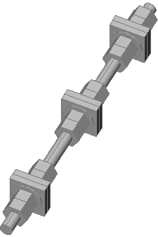
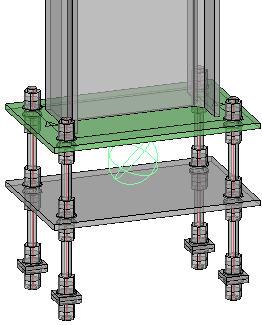
It is now possible to draw simple and complex rods with the same tools that are used for drawing bolts, nuts and washers.
A rod can tighten up to 3 groups of materials where a normal bolt can only tighten 1 group of material. A maximum of 4 parts can be activated on each side of the material for a total of 8 parts per tightening group. A group can also be a standalone combination of (square) washers and nuts such as for anchors embedded in concrete. In this scenario the group does not fasten any plates together.
In the rod assembly settings we can choose the type of part to be used in each position, and when drawing the actual rod we can activate or deactivate individual parts as needed.
Additional bolt part types
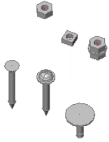
It is now possible to add the following parts to the library and draw them as part of a bolt assembly:
- Square nuts
- Square washers
- Square head bolts
- Cylindrical head bolts
- Domed head bolts for rivets, screws or nails
- Sharp ending for screws
 Standalone nuts
Nuts and washers can now be drawn without a base bolt. We can still use the same bolt object for this which gives us all the bolt object advantages such as ease of drawing and editing, automatic hole creation and unified handling in reports and exports.
Standalone nuts could be solitary, or a combination of nuts and washers in case they are to be used with custom-created bent rods.
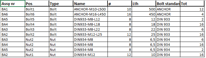
Bolt assembly and bolt part numbering
It is now possible to let Parabuild automatically number bolt assemblies and their individual parts: base bolt, nuts and washers.
Different prefixes and start numbers can be chosen for assemblies and each bolt part type. If enabled, bolt numbering will automatically run during the existing numbering commands.
Numbered bolt assemblies and parts can be used in annotations and bill columns, and can be useful on shop drawings (for shop bolts), GA drawings (field bolts), for shipping and on-site use for easy labeling and identification.
Some new reports were added to let you make use of these numbers :
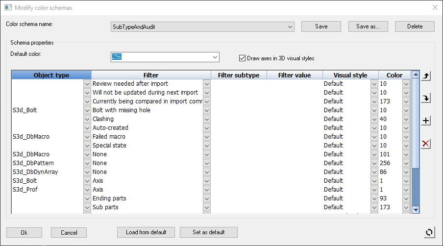
Manage colors in 3D
Parabuild currently chooses the colors for welded parts, colliding parts, etc. It is now possible to adjust the colors in the view management yourself, based on almost all properties of the parts. This allows you to do much more with colors, such as creating your own color scheme that gives all elements a color based on their phase.
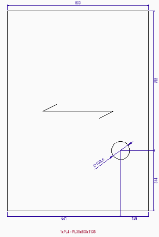 Add span symbol to regular plates
A span symbol can be activated for plates to indicate a certain direction on the workshop drawing. The span direction can be used to determine the load bearing direction of grating and floor panels, grain direction for wood, or the direction of fibers in fiber reinforced plastics. Reference geometry can be chosen, and additional angle specified. The span symbol can be set to affect part numbering as well.
This tool can also be used to influence the orientation of the coordinate system of a plate without adding the span symbol on the shop drawings.
Length optimizer can now generate complete reports
The profile length optimization command calculates an optimized solution for cutting profiles from readily available stock sizes.
The optimizer command can now write a full report of the items by merging the chosen stock length report with another report containing the parts that were not included in the stock lengths. The complete report could for example be used for an advance bill of materials.
Product codes
Product codes can be used to uniquely identify items that may be standardized or available off-the-shelf and have an associated code. Product codes can be proprietary formats, or they can be standardized like UPC or EAN codes.
When a product code is needed for reports or annotations, Parabuild will look it up in one of these sources:
- The product code property of the part, if it was set. This property can be automatically assigned using the “Standard Parts Library”
- For bolt assemblies the product code property in the bolt assembly library
- For bolt parts the product code property in the bolt parts library
- For profiles the Product code in the section table of the profile
- Lastly, the product code tables that are stored in the library
Annotation style changes
Annotation styles and groups are now split: styles no longer need to be part of a group, and multiple groups can refer to the same annotation style. this makes annotation styles much easier to configure. Annotations with multiple template string inputs (e.g. template strings above and a divider line) are easier to configure. When there are multiple template string inputs, such as shop drawing settings and annotation style, it is now possible to assign which of the inputs gets priority.
Assembly name and description
Assemblies now have a name and description property which is useful to be used in bills. These properties can be a template string combining any number of properties, such as the structural type, material, main part name, etc…
This property also can be automatically assigned using template drawings or by structural type classification.
When the property was not individually set the default template string is used for that assembly, this default can be determined by the user.
When neither the assembly property or drawing default was set, the name of the main part is used instead.
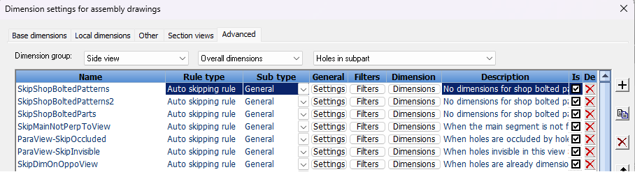
Improved rule-based automatic dimensions
Aside from convenient and simplified dimension settings, Parabuild already had a system for the user to add additional dimensioning rules.
However this system was too difficult to use and too limited, so it has now been redesigned.
The new rule-based system is more user friendly and has more powerful functionalities.
These are some of the characteristics of the new auto-dimension system:
- A sequential rule based system similar to the one in AutoWeld and the contour marking system.
- Custom rules can easily be inserted without having to understand the automatically generated dimensioning rules.
- Aside from the preexisting geometric shop drawing-specific filters, now also the general object-based filter system can be used to detect and dimension specific scenario’s. These filters can include shape, size, properties, structural type, etc…
- Intercept only the cases that are not to your liking and leave the remainder to the rules that were automatically generated based on general dimension settings.
- Automatically generated rules can be adapted or copied. Custom rules, whether newly created or adapted from automatic rules, can be preserved when the automatic rules are reset after a change in general dimension settings
- Various new dimension options to better fine-tune the result.
New bill for printing a sticker per assembly
With the new bill Stickers for assemblies you can have a sticker printed for each assembly.
The BOM creates one page per sticker to send to a sticker printer. A sticker contains much more information than a scribed number and less scribing means your beamline can finish a member faster.
Improvements to bills/reports
- Reports can have other reports automatically attached so that the combined report shows up as a single file. The columns are not required to match up
- New default bills were added called Welders checklist, Bolt parts, and Assembly and bolt parts combined were added
- Pre-set template strings: Configure template strings for use in reports and drawing BOM columns which allows for more advanced contents in the bill
- Excel templates for reports can be more flexibly configured, for example to determine the cell formats and to determine where the columns get inserted.
Other new features
- This version of Parabuild is compatible with BricsCAD V24
- The export to step file feature now has the option to write a step file for each assembly in the drawing.
Previously it was only supported to write a step file for each part. For now this feature is only supported when the BricsCAD Communicator module is installed and licensed.
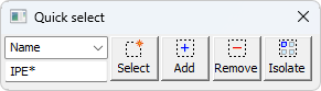
 Some improvements were made to the Quick select : it is now possible to filter on all properties with a certain value and with a wildcard (*).
If you need to search all IPE shaped section then use the text IPE*
- Improvements for the weld seams in 3D and the weld symbols in 2D
Weld seams with a limited length can now also be drawn in 3D and also indicated in 2D
Improvements were made to reduce the number of weld symbols on the shop drawings - An additional option for automatic numbering of 3D parts was added: main parts that do not have welded parts can optionally adopt the part number of the main part.
- Improvement for the Dxf file of unfolded parts
With a new setting you can have the folding lines drawn in the Dxf file.
The folding lines are drawn on both sides of the plate and you can also give the fold lines a limited length.
- Parts now have a property that allows skipping participation in clash checking, and a property for clash volume to be ignored
- When bolts are set to shop (or field) bolted, small parts are now automatically attached to (or detached from) the assembly of the larger part. Likewise when parts are joined into a single assembly, and there are bolts between those parts, they are automatically set to shop bolted.
- Shop bolts have better handling on drawings, reports, and drawing bills
- The bolt assembly library has additional properties available that automatically get assigned upon bolt creation
- The macro dialog box for stairs and railings can now save and load the entire configuration of the values on the dialog box.
There are many more features in this release
A full list of all the features and where to find them in Parabuild itself can be found in the Parabuild reference manual