In this release, the main focus is on increasing efficiency in the workshop.
The attached part contours in DSTV and DXF output were improved considerably. Options to draw partial contours reduce scribing time without sacrificing the usefulness of the contours. Contours are also optionally added to the attached parts, not just the main parts (new for DSTV, this was already possible for DXF).
When the part numbers of the attached parts are to be scribed as well, Parabuild will automatically search a suitable location for those tags to avoid collisions and ensure readability.
There is a new option to consider contours while numbering so that each part with unique contours gets a different part number. When this option is used, parts will no longer need to be scribed with the assembly number, which further reduces the scribing time.
These new options can not only reduce scribing time for the machine but will also help reduce layout marking and avoid errors, offering significant efficiency improvements on the shop floor.
We are also introducing support for the KISS format. This format has been in use for a long time and is a valuable format for transmitting fabrication data to MIS/MRP/ERP software solutions.
Shop bolt treatment was also improved, and there are now bolt bills on assembly drawings for shop and/or field bolts. Which assembly a field bolt belongs to can be influenced in several ways.
Many new object properties were added, and many smaller improvements were made. Read below for more information on the new features.
Overview of the new features in version 5.1
Click on a topic to read more about it, or scroll down to see all of the information about the new features.
Check contours when numbering parts
New features for DSTV file generation
New features for DXF file generation
KISS format
Better support for shop bolts
Add bolt bill on assembly drawings
Influencing to which assembly a bolt is attached to
New project data
New sheet properties
New plate/profile properties
New bolt properties
Hole annotation override
Skip drain/vent holes in shop drawings
Connect view to a camera
Hatches for floor plates
Others
Check contours when numbering parts
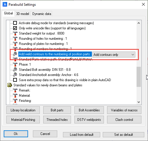
This new option can be found in the Parabuild general settings dialog box.
When contours are checked while numbering, then the location of a part relative to the attached parts in that assembly may influence its part number.
When contours, as well as tags, are added to the numbering, then the part number of each attached part is also considered by the numbering and may also cause a different part number if it differs.
The advantages of enabling this option are :
- Less complexity in the naming of DSTV and DXF files, because the part number will not have to be combined with the assembly number anymore.
- The assembly numbers will not have to be scribed on the part in order to uniquely identify the part.
- There is less potential for confusion when each part with different scribing has a different part number
- Some MIS/MRP/ERP solutions do not support the combination of the part number and assembly number for the CNC files. This issue can be avoided by enabling this option.
One minor disadvantage of this option is that it may result in more part numbers and thus more shop drawings for single parts. The amount of assembly numbers/drawings will remain the same.
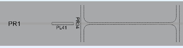
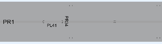
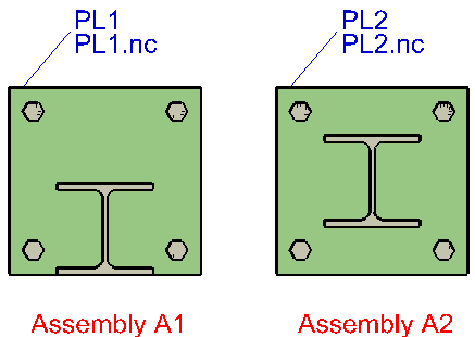
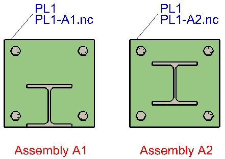
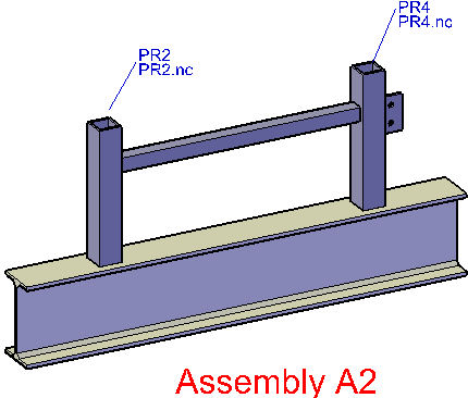
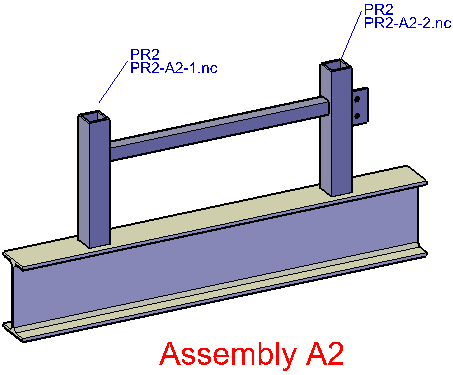
Parabuild ensures you will get different NC files (DXF & DSTV) for parts with different contours, whether the option to consider contours in numbering is enabled or not.
This is important because if detailing software generates only a single file for parts that may have different contours, this can result in loss of material and errors on the shop floor if the situation is not discovered before welding.
The following illustrations show the difference in numbering when the contours in numbering are activated or deactivated. This example mentions DSTV filenames, but the same goes for DXF.
New features for DSTV file generation
- Arcs in the cuts of profiles and plates are now supported. Sometimes this is done by approximating lines, but actual arcs are used when possible.
- Bevels/Weld preparations are now supported for profiles
- Countersunk and blind holes are now properly exported in DSTV
- The corner treatment for contours was improved (partial contours)
- Contours are now supported on sub parts (including plates)
- The automatic location of tags on the parts has been improved: they are drawn close to the contours and get automatic placement so that the text avoids collisions with holes, contours or other tags.
- Contours are exported as arcs where possible
- There is an option to export contours as Punch and/or Powder (block KO and/or PU)
- When the option to check contours while numbering is enabled, then we can reduce the number of letters to be scribed on the parts (see the numbering topic for more about this)
- The DSTV filename now only includes the assembly number when the contours differ for two parts with the same part number. When multiple parts within the same assembly and with the same number have a different contour, they get an incremental number after the assembly number as well. (Note that if the option to check contours while numbering is enabled, this will not be needed)
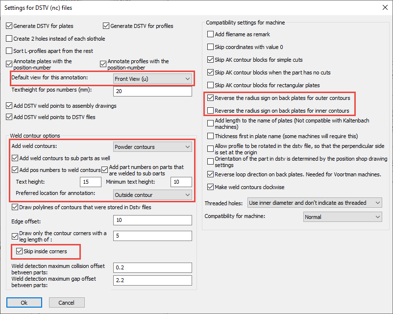
Here we outline the new options that were added to the DSTV dialog box :
Default view for this annotation : To choose on which side the part’s number should be scribed when there is enough space available
Add weld contours : To choose between either punch, powder, or both. If you choose both, then all of the contours are added to the DSTV file twice.
Add weld contours to sub parts as well : If disabled, only the main part of an assembly will receive weld contours. If enabled, all parts will receive weld contours.
Add pos numbers to weld contours on sub parts: If disabled, only contours on the main part will get number tags. If enabled, contours on sub parts will also get number tags.
Weld contour text height : Sets the default height of welded part numbers text (this is a separate value from the main part’s number).
Weld contour minimum text height : If the part number text would fit somewhere (especially inside the contour) if it were of a smaller size, then a reduced height will be used. With this option you can choose the minimum text height that is allowed for scribing.
Weld contour preferred location for annotation : Default behavior is to place this annotation outside of the contour. You can choose to prefer placement inside of the contour, but if the text is too large to fit in the contour then it will be placed outside of the contour anyway.
Skip inside corners : Inside corners will occur with more complex contour shapes, but may not be helpful when laying out the parts/welding. You can skip these corners with this option.
Reverse the radius sign on back plates for outer contours : Compatibility setting for some machines and software.
Reverse the radius sign on back plates for inner contours : Compatibility setting for some machines and software.
New features for DXF file generation
- Instead of the full contours, partial contours can be drawn to reduce scribing time.
Dxf files new options - The automatic location of tags on the parts has been improved: they are drawn close to the contours and get automatic placement so that the text avoids collisions with holes, contours or other tags.
- The DXF filename now only includes the assembly number when the contours differ for two parts with the same part number. When multiple parts within the same assembly and with the same number have a different contour, they get an incremental number after the assembly number as well. (Note that if the option to check contours while numbering is enabled, this will not be needed)
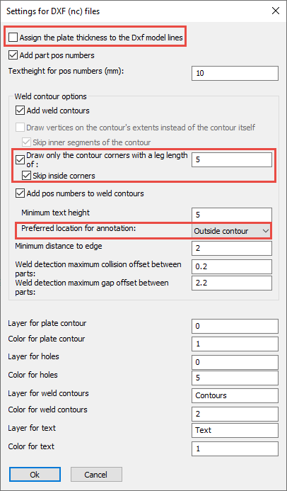
Here we outline the new options that were added to the DXF dialog box :
Assign the plate thickness to the DXF model lines : When active, the thickness of the plate will be assigned to the model lines in the DXF files. This creates a semi 3D model and the machine can know the required thickness of the plate this way. Some machines can’t read the DXF file when this option is active.
Draw only the contour corners (with specified line length) : When this is active, only the corners of the contour are scribed to save the machine processing time.
Skip inside corners : Inside corners will occur with more complex contour shapes, but may not be helpful when laying out the parts/welding. You can skip these corners with this option.
Preferred location for annotation : Default behavior is to place this annotation outside of the contour. You can choose to prefer placement inside of the contour, but if the text is too large to fit in the contour then it will be placed outside of the contour anyway.
KISS Format
The KISS format (Keep It Simple Steel) is a format for exchanging construction data with MIS, MRP and ERP software.
This is a short explanation for each option :
Export assembly sheets : If you enable this, then PDF files are generated in the subfolder “Fabrication” for the available assembly drawings.
Export Dstv files : If you enable this, then Dstv files are generated in the subfolder “CNCData”.
Export field bolts : Shop bolts are always exported, field bolts are optional
Export nuts and washers : Nuts and washers get separate ‘detail parts’ with this option
Export labor info : Will calculate and export labor data for all holes, cuts and burns
Allow accumulation of labor : Should normally be disabled: according to KISS specification the counts should be per piece. But some software products expect KISS files with accumulated labor so this is available as an option.
Sequence template : Optional, to make the sequence field a combination of phase&sequence. Currently supports %Sequence% and/or %Phase% ex: “%Sequence% – %Phase%”
Section name column keywords : Columns with these keywords will be used for the section shape’s name. These keywords are accessible in the profile section tables.
Use assembly number for sheet name when the assembly does not have a shop drawing : When no sheet was found with this assembly on it, the Assembly number can serve as a place holder
Default drawing number when assembly has no shop drawing : This is used when the option ‘Use assembly number for sheet name‘ is not active.
Shop bolts
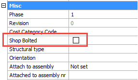
If you enable this bolt property, then the bolt will be drawn on the assembly drawing and added to the bolt bill.
The bolt will act as if it is welded to the assembly.
This property will also influence the numbering of the assembly.
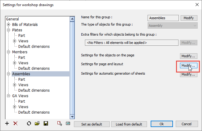
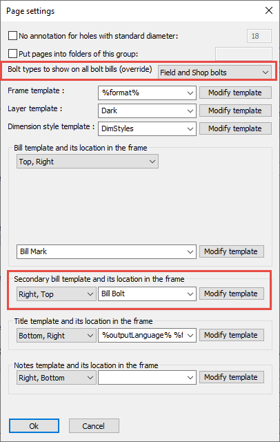
Add bolt bill on assembly drawings
A secondary bill can be added to the shop drawings. On assembly drawings, this is a bolt bill by default.
You can change the bill template file, and also the types of bolts to be included here :
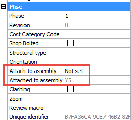
Influencing to which assembly a bolt is attached to
A field bolt is considered to be attached to a specific assembly, even if it connects 2 or more assemblies together. We call this the reference assembly of the bolt.
This reference assembly matters because it will determine on which assembly drawing the bolt will appear.
(a field bolt will not appear on 2 assembly drawings to avoid counting the bolt more than once)
The simplest way to influence the reference assembly of bolts is with this priority list :
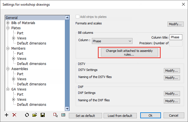
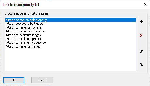
With this priority list, you can influence the automatic assignment of reference assembly of all bolts.
In exceptional cases where the automatic assignment based on the priority list is not sufficient, it is still possible to manually set the reference assembly in the properties of the bolt.
In this property, we can choose the assembly “Closest to bolt head” or “Closest to Bolt end”. This will effectively override the main priority list.
New project data
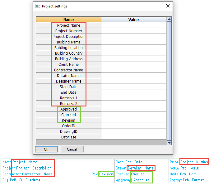
The project data now includes 15 fixed fields, in addition to the dynamic fields.
These fields can be modified in the Project data dialog box. These 15 fields are used not only for filling title blocks in sheets, but also for writing project data when exporting data such as KISS files.
In the below image, the fixed fields are indicated in red.
When using these fields in a template title block, it is possible to use the text “Project Name” or “Project_Name”. Both texts will be replaced by the actual project name.
Some dynamic field examples are indicated in green. More fields can be entered freely.
The dynamic fields can be added by simply typing them in a title template file, and saving that file.
When you open the Project data dialog box, all of the title blocks that start with the current language (eg English*.dwg) will be loaded and all text fields are analyzed. The non-standard fields are then added to the list of fields.
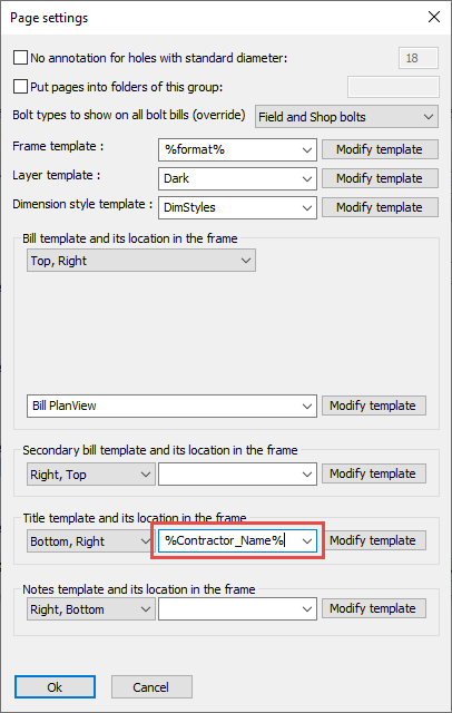
It is now possible to use project data fields in the template filenames for sheet generation.
The field will be filled with the current project data value of the current 3D drawing, while Parabuild is generating sheets.
The field name must be preceded by the % symbol and must end with the % symbol.
Spaces can be replaced by the underscore symbol.
A use case example for this would be the %Contractor_Name% field for the title template’s filename. This will allow you to let Parabuild use a specific title template for each contractor.
These are the steps you need to do for this to work :
- Enter the contractor name in the project data
- Create a title template drawing for the contractor with the contractor name as the filename
- Set the %Contractor_Name% field for the title template filename in the shop drawing settings.
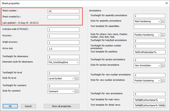
New sheet properties
There are 3 new properties available for sheets :
By default, the sheet number is the same as the sheet name. But this number can be changed manually.
The created on date and time is filled automatically.
New plate/profile properties
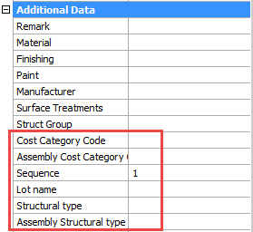
These are all the new properties for profiles, plates, structures and volume objects.
Cost Category code: These codes are usually used for estimating and quoting, but can also be used to trace parts from estimation to production and ERP/MIS software. (PbColCostCategoryCode and PbColAssemblyCostCategoryCode)
Sequence: The erection sequence of an assembly. (PbColSequence)
Lot name : The lot that the part belongs to. (PbColLotName)
Structural type : For example : Bracing/Rafter/Stringer/Handrail/Post/etc…. (PbColStructuralType)
Assembly Structural type : For example : Stair/Railing/etc…. (PbColAssemblyStructuralType)
Beam camber (profiles only) : The camber to be used for the beam. This value influences the position number of the beam. (PbColBeamCamber)
When using properties as columns in template bills, in settings or in adaptive annotations, the variable name is placed between % symbols. Example usage : %PbColSequence%
New bolt properties
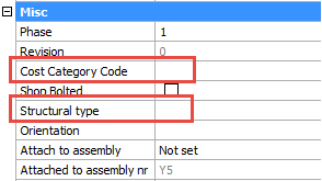
Cost Category code : For estimating and quoting. (PbColCostCategoryCode)
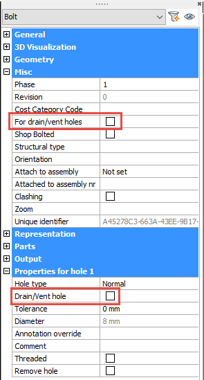
Hole annotation override
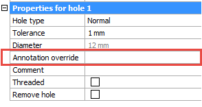
A new property was added for holes, which allows you to set a custom annotation text for a hole.
The property is only modifiable from the properties of the bolt.
This text will appear on position shop drawings.
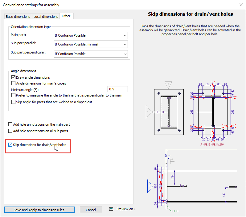
Skip drain/vent holes in shop drawings
When active, drain/vent holes will not receive dimensions on the assembly shop drawings.
The drain/vent property of these holes needs to be activated for this to work.
Connect view to a camera
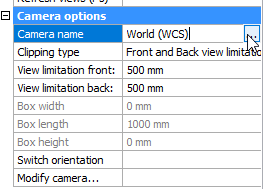
It is now possible to connect a view to a different camera.
This is a useful tool to fix disconnected views.
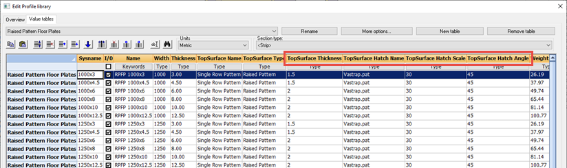
Hatches for floor plates
The hatch pattern in the section tables was fixed. New flat bars drawn from a table that has these special hatch columns will now automatically get this surface treatment and hatch on the top face.
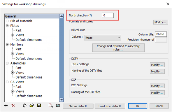
Cardinal directions for 2D drawings
The shop drawings can optionally use the cardinal directions for views (this is a pre-existing functionality).
Parabuild uses the current drawing’s NORTHDIRECTION variable to know this direction.
This variable can now be modified in the shop drawing settings as well :
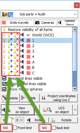
The isolate visibility buttons will now use the front/back values to determine which parts should be isolated