Version 6.0
Structural types
The purpose of structural types is to assign type names to parts and assemblies so that those types can be used to automatically assign properties, define behavior specific to that type, or select objects based on their type.
The most obvious examples of structural types are columns and beams.
During or after the structural types are assigned to parts, we can use several tools on these parts, such as :
- Automatically assigning properties to the part. For example, assigning numbering prefix B for Beams and C for columns.
- Automatic selection of all the parts with a particular structural type
- Define a CNC scribing style specific to a structural type
- In the near future, many more applications for structural types will be implemented
Assigning structural types can be done in a number of ways :
1) Assigning automatically during numbering
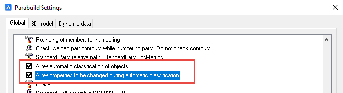
When this option is enabled in the Parabuild Settings, Parabuild will automatically assign structural types to all parts when the model is numbered.
This value is enabled by default when you install Parabuild.
However, if you have updated Parabuild from an older version to v6, or if you open a drawing that was saved with a Parabuild version older than v6, then this setting will be disabled. By disabling it in older projects we can ensure that the numbering of older projects will not have a mix of old and new numbering prefixes.
If the numbering was done premature before the project was finished (for example a bill was generated), then the assigned structural types might not always be the best.
To solve this either run Classify parts on those objects, or disable automatic classification and run Classify parts when the model is (mostly) ready.
2) Assigning automatically on demand
You can use the Classify parts command to purge the previous classification of parts and automatically classify them again.
3) Assigning manually
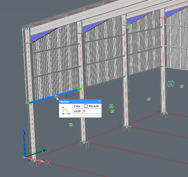
You can use the Properties panel to assign structural types to parts.
Many Structural types can be detected and assigned automatically.
However, for most structural types the connections between the different members are used to determine the type of the parts.
The structural type detection uses the connected bolts, welds and macros to learn more about the part.
For example for a profile to be classified as a beam, it will need an end-connection on both sides.
Columns on the other hand are more quickly classified as such because their upright position alone is enough to distinguish them from all the other structural types.
Therefore it is best to automatically classify the parts when the 3D model is (largely) finished.
Once a structural type is assigned (manually or automatically), then the numbering will not try to classify the part anymore.
If you want to re-assign the structural type of parts that already have a structural type, then use the Classify parts command.
You can read more about Structural types here.
Classify parts
Command : PrB_Classify
This command can automatically classify all parts or a portion of the parts.
Many Structural types can be detected and assigned automatically.
However, for most structural types the connections between the different members are used to determine the type of the parts.
The structural type detection uses the connected bolts, welds and macros to learn more about the part.
For example for a profile to be classified as a beam, it will need an end-connection on both sides.
Columns on the other hand are more quickly classified as such because their upright position alone is enough to distinguish them from all the other structural types.
Therefore it is best to automatically classify the parts when the 3D model is (largely) finished.
This command can re-assign all parts, or only assign parts that do not have a structural type yet.
Read more about the Classify parts command here.
Modifying structural types
Structural types can be modified or new types can be added.
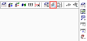
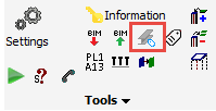
The structural types modification dialog can be accessed from the Parabuild Settings command.
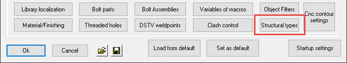
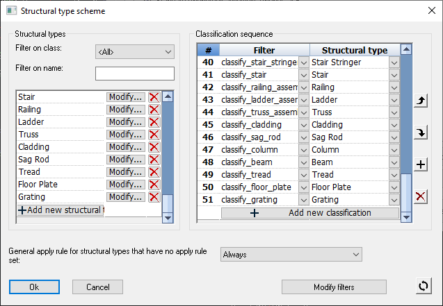
Read more about the Structural types here.
Filters
The purpose of filters is to identify specific objects in the model based on a set of rules..
The structural types rely on these filters to classify objects, but that is not the only use case for filters.
Filters can also be used in general to find certain types of parts.
The CNC contour settings for example also use filters to assign different contour options to the type of part.
Filters can use the part properties and even geometrical traits as condition for passing the filter.
In the near future, many more applications for filters will be implemented
The filters modification dialog can be accessed from the Parabuild Settings command.
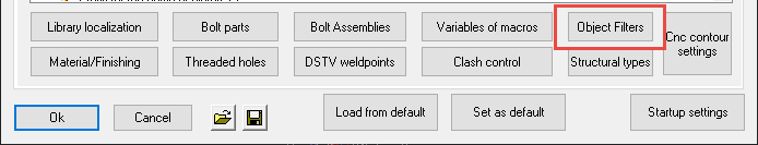
Read more about the Object Filters here.
New match lines capability for DXF and Dstv + contours update
The following new capabilities and updates were done to both DXF and Dstv export :
- Scribing of contours has been updated with more capabilities such as choosing different scribing on main parts than on sub parts, only scribe outer extent corners to minimize the amount of corners, and choosing punch marks instead of scribing of full lines or corners..
- In addition to the scribing of sub-part contours, now hole matching lines can also be automatically scribed. The hole axis is projected, and here both the main member and the sub-part can be marked with a short line or a punch mark. Those matching lines/marks can then be simply matched up in the shop to position the parts on the assembly.
- Filters and structural parts can be used to configure which situations should get certain types of scribing. This allows for great user control in the fully automatic scribing system. For example, the user could specify that main members get only punch marks to save time on the beamline, but plates get corner contours with hole match lines for clarity. Another example: a different type of sub-part could get a different style of contour scribing on the main part.
These capabilities will offer the draftsperson and the workshop the following advantages :
- These advanced scribing options replace the manual scratching/marking when laying out the steel, saving significant man hours in the shop.
- Contours, punch marks and hole matching lines are generated directly from the 3D model and can reduce mistakes on the shop floor.
- The capability to use punch marks on some types of parts coupled with scribing on other types can save time on the beamline by using punch marks there, while still having the option to use full or corner contours and scribed hole matching lines on plates.
- Scribing contour and/or part numbers can be skipped entirely for specified situations. This offers further opportunities for optimizing the utilization of the machines in the shop.
- Automatic scribing options can be configured based on the type of part. These settings only need to be configured once, and after that CNC files for the whole model can be generated automatically. This will save the draftsperson time in not having to do changes manually.
All together these features will increase productivity of the drafters, shop floor staff, and machines in the shop.
You can read more about CNC contour settings here.
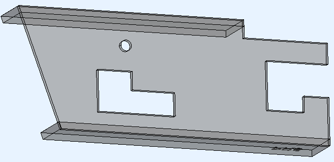
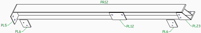
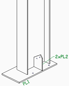
Here are some examples of what is possible with contours and match lines in different situations.
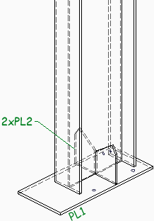
|
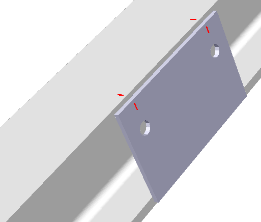
An example baseplate and gusset plate where only match lines were enabled |
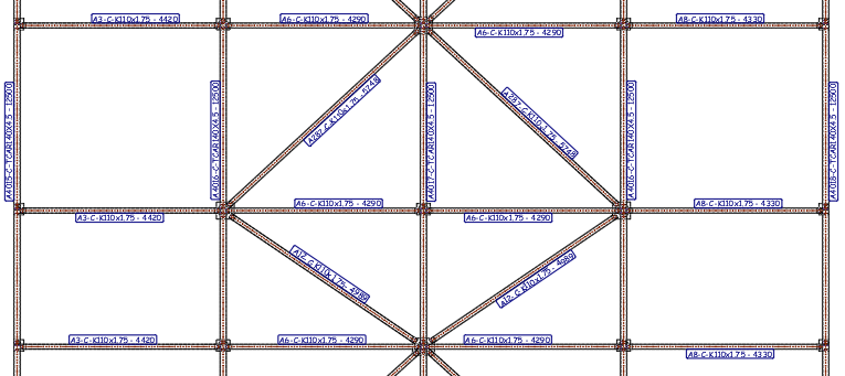
|
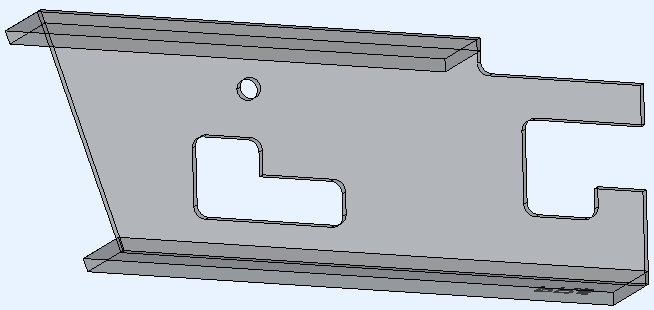
An example with match lines on the plates, and punch marks on the profiles |
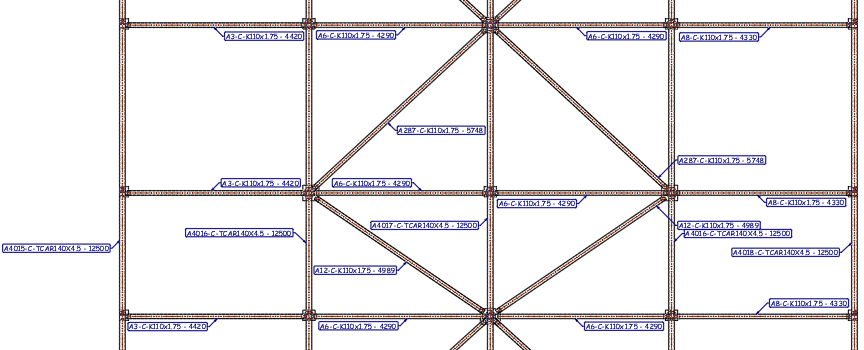
|
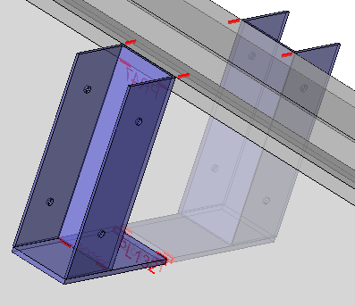
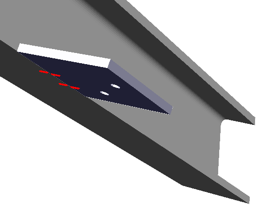
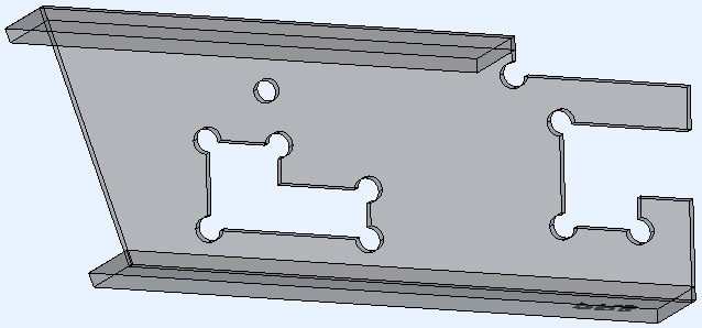
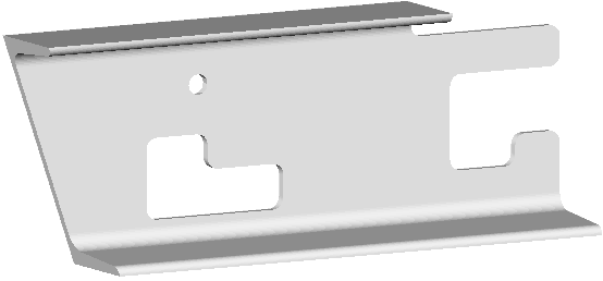
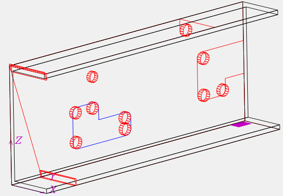
An example of brackets where match lines are transferred to the top flange automatically. There are also sub parts that have contours for other sub parts, this is optional and can be turned off. |
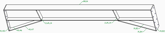
|
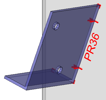
An example of corner contours combined with hole match lines |
|
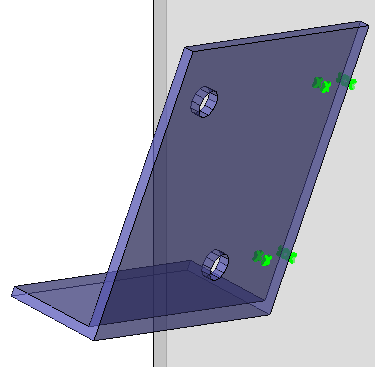
The same example as above, but with punch marks on both the main part and on the attached part, no contours and no part numbers |
|
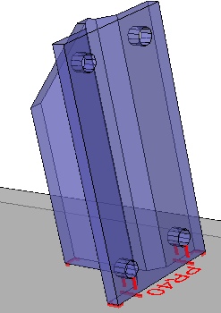
Another example of corner contours combined with hole match lines |
|
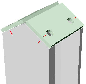
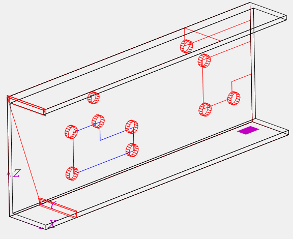
Hole match lines were transferred to the flange automatically |
|
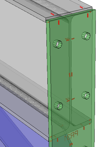
Example of a haunch connection end-plate, with it's hole match lines transferred to the flange. The scribing on the outside of the end-plate can be turned off |
|
Example of a toe plate where the hole match lines were transferred to the flange |
|
Example of double end plates where hole match lines are transferred to the flange |
New DSTV options
The following new capabilities were added to the Dstv command :
- Export wraparound-style plate for pipe/CHS to DSTV files
- Automatically add fillets to notches, or replace cuts/notches with drill holes (highly configurable)
- A new option that filters out small planar cuts using a tolerance. Thanks to this option, the machine will not block on double saw cuts on one end of the profile if one of the cuts is negligible.
Dstv Cuts / Notches
Consider the following Dstv end-results that are generated automatically from the same 3D model:
This is the example 3D model that incorporates the 3 different cut types. This is the original unmodified model thus generated with the notch corner type None
The example 3D model generated with the notch corner type Fillet arc enabled

The example 3D model generated with the notch corner type Corner arc enabled
The example 3D model generated with the notch corner type Corner hole only enabled.
In some Dstv viewers we can't see the difference between the arc and the hole because the end-result is the same.
The second image shows a view with a different representation for holes compared to arcs.
Notch drill hole type - This option will cause drill holes to be placed on top of fillets and/or corner arcs. This is done both for 3D modeled arcs and for those automatically added using the "Notch corner type" setting.
This option can be used in the following scenarios:
- The machine can't cutout the current cut type. By adding holes to the cut corners, the machine will drill a hole for each inside corner. This in turn reduces the amount of manual labor still needed to cut out the remainder material manually.
- The machine can do the cut-out, but it takes too much time. Only drilling the holes for each inside corner of the cuts will reduce the time needed per cut.
- When a cut is removed, this can result in excess material falling off the part when the last part of the cut is done. Care should be taken that this material does not fall on the moving drill/mill. Depending on the machine's programming for this situation, the machine operator may want to deal with this problem himself/herself. A way to avoid this issue entirely is to not cut out the material but to use this option to only add holes in the cut's corners.
Do note that this option will add holes on top of the corners of the cut, but the cut themselves will still be added to the Dstv file.
The machine operator will still have to instruct the machine to not process the cut if you want to use this option in the above scenarios 2 and 3.
In scenario 1, we are assuming that the machine will automatically warn that the cut can't be processed by the machine.
The following drill hole options are available :
- Never - Drill holes are not automatically added
- For fillet arcs - A drill hole is added only on top of fillet arcs
- For corner arcs - A drill hole is added only on top of corner arcs
- Fillet and corner arcs - A drill hole is added on top of both fillet and corner arcs
Consider this example 3D model :
This is the model as it is drawn in Parabuild
This is the end-result after generating the Dstv with the option Drill hole type For fillet arcs enabled.
Extra holes are added on top of the existing arcs.
You can read more about cuts and notches in the DSTV NC Settings topic.
Floating network licenses
A floating Parabuild license can easily move from one user to another user over the internet. The floating license is only available for Full versions of Parabuild and comes at an additional cost.
In Parabuild, a floating network license does not require the installation of a network server.
This service is provided by Parabuild directly over the internet.
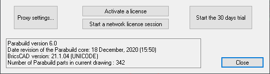
Read more about the floating license in the License management topic.
Feeding excel values to Macros and arrays
Command : PrB_FeedExcelToMacros
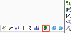
This command can be used to feed cell values from an excel file directly into macros and arrays in a Parabuild drawing.
A mapping file can be used to reduce the need for having to repetitively enter names, but the mapping file is not a requirement.
You can download and use this sample template and accompanying excel files to test out this command :
- Template drawing of a portal frame with cladding sheets
- The excel feeder file that was created to feed values the portal frame template
- The excel mapping file that was created to map the values to the macros and arrays in the portal frame template
|
|
An example template drawing before applying the excel values |
An example template drawing after applying the excel values |
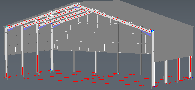
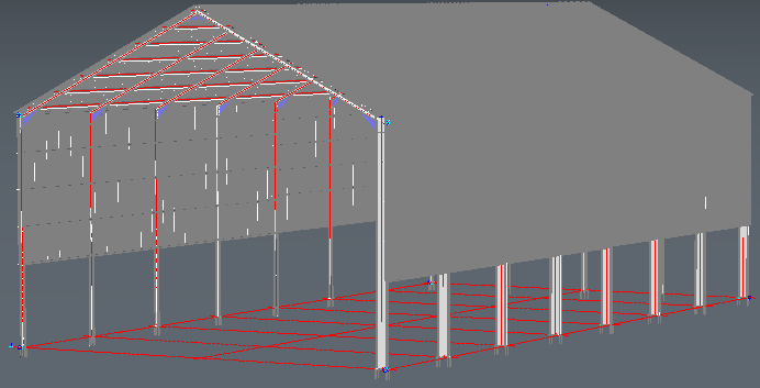
In this example the excel file(s) changed the roof height, enlarged the structure, changed the number of portal frames, modified the side rails and did changes to the apex and haunch connections.
Read more about the Feeding excel to macros command here.
Dark theme
Dark theme is now supported for the ribbon and toolbars.
The correct color scheme for the icons are loaded automatically without intervention.
The color theme can be changed with the variable COLORTHEME.
If you encounter a problem with the Parabuild toolbars or ribbon, you can use the commando PrB_Menu to reset and reload all Parabuild toolbars and ribbon.
New Materials table
This table is used by Parabuild to find out what the weight factor of the materials are.
It also allows us to automatically assign certain properties at the time when a material is assigned to a part.
Each row in the table represents a material.
The grade is combined with the material, that is why we have several different entries for steel in this table.
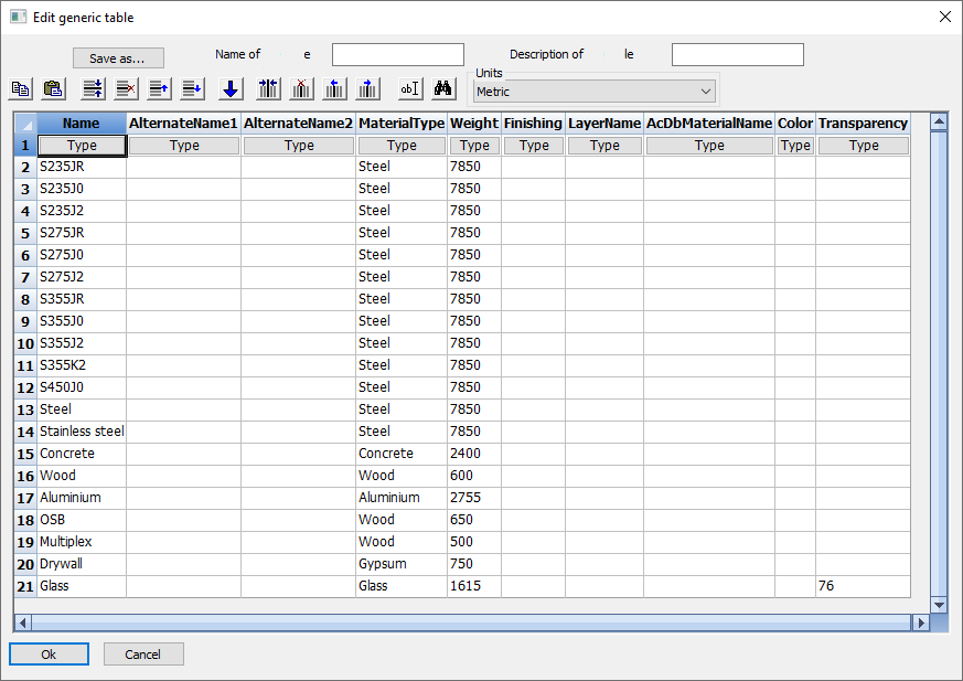
You can read more about the materials table in the Material / Finishing topic.
Curved railings
The macro and array system in Parabuild have been expanded to support curved railings.
A curved railing can be drawn with the regular Railing command, by selecting an arc or an edged of a curved profile.
For now, only 1 curved railing type was added to the railing command.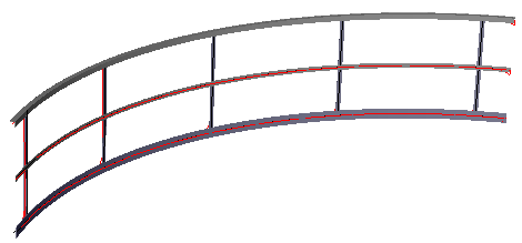
Macros that use a planar surface now also support other surface types
This new feature applies to all macros that use a planar surface.
When Parabuild prompts you to select the planar surface, you can also select a cylindrical or spherical surface.
While the macro is created, the tool will first calculate the intersection between the profile and the sphere.
Then, the planar surface is calculated by making it tangent to the sphere. This planar surface is then used by the macro to position the parts.
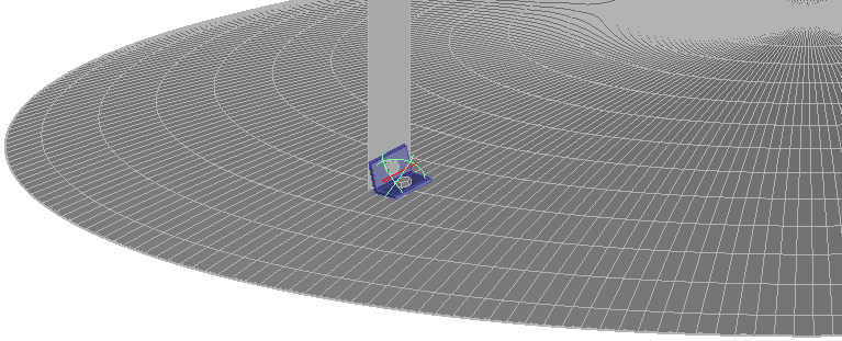
Example of a clipangle drawn against a spherical volume, which could be the roof of a tank
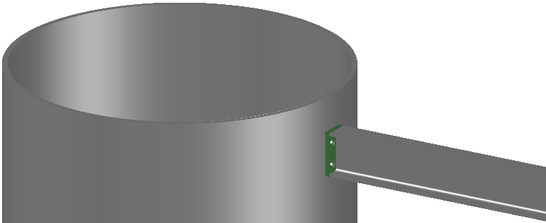
Example of an endplate drawn against a cylindrical profile
You can read more about the Macros to a planar surface here.
Behavior change to double-clicking parts and macros
When double-clicking a macro or a part, the corresponding macro will be opened in the Review Macro dialog box.
However, pressing the SHIFT and/or CTRL keys while double-clicking will determine the behavior of the action.
These are all the different behaviors, with an example drawing of what would happen when double-clicking a side rail :
This is a Parabuild portal frame template that was fully parameterized, and we're double-clicking one of the side rails.
- Double-click without SHIFT nor CTRL pressed - Only the macro of the selected part will be reviewed. In the example, just the macro of the single side rail will be reviewed.
- Double-click with SHIFT OR CTRL pressed - All of the parts that are dependent on the same array will be reviewed. In the example the 4 side rails and the array itself will be reviewed.
- Double-click with SHIFT AND CTRL pressed - The top owning macro of the part that you selected will be opened, together with all of its sub-macros. In the example, the top owning macro is the portal frames macro so the entire drawing will be reviewed. That is because the entire drawing is fully parameterized.
New option for adding position details on the assembly drawing
The assembly shop drawing generation now has a new option for adding all of the position details on the shop drawing.
This will of course result in a larger drawing, but there is also the possibility to skip the position details of the main part.
All of the main part's dimensions can also be activated on the views of the assembly itself so that all of the information for fabrication is still there on the sheet in case you would use this last option.
You can find this new option in the Settings for automatic generation of sheets dialog
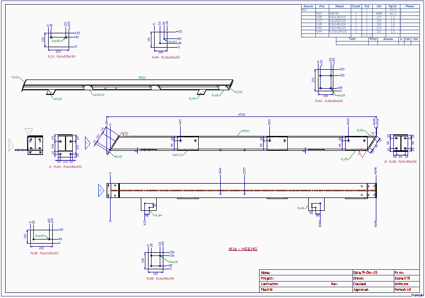
A drawing with position details on the assembly, but without the main part position detail.
New view option for shop drawings : annotate the isometric view
Adding the annotations to the isometric view will help with more quickly identifying parts of the assembly.
This options is adjustable in the Annotations and dimensions dialog box for the view.
New view option for views : do not show lines occluded by the part itself
It can be activated from the Objects to be copied from 3D to 2D views dialog.
By activating this, many of the hidden lines are cleared, uncluttering the view.
To illustrate the differences, here are examples of the 3 different hidden line options that are available :
|
|
|
All hidden lines disabled |
All hidden lines enabled |
Hidden lines are enabled and the new 'skip occluded by self' option as well |

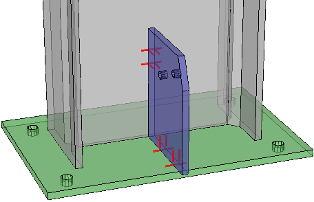
With the hidden lines option active, we can see the part behind the column.
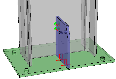
With the occluded by self option active, most of the clutter of invisible lines will be cleared while still keeping hidden parts visible.
This option will be very useful for the 3D isometric view on shop drawings.
The new hidden line method will help clarify the assembly's composition.
New option for automatic tags : sticky tags
Sticky tags are tags that will stick to the edge of the annotated part, so that a leader is not necessary.
When activated, Parabuild will automatically decide for each tag whether to make it sticky or not. A tag will only become sticky if the part has an edge that is long enough for the tag to stick to, without intersecting any other lines.
This option can be activated in the Annotations and dimensions dialog box for the view.
|
An example view with sticky tags enabled |
|
The same example view with sticky tags disabled |
|
An example view with sticky tags disabled |
|
The same example view with sticky tags enabled |
New options for the relation between the thread and the shear plane of bolts
The Bolt Assemblies have the following new options :
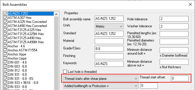
These options allow you to choose the location of the thread end, at one of these 3 locations :
|
|
|
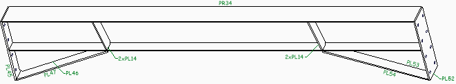
Thread starts anywhere, it passes through the shear plane in this case |
Thread starts after the shear plane |
Thread starts after the gripped parts |
For more information about this feature, see the Bolt Assemblies topic.
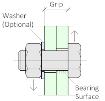
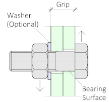
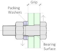
New bolt property : number of filler washers
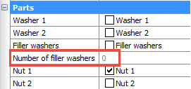
When the Filler washers (Packing washers) option of the bolt is enabled, and the shank of the bolt extends beyond the Grip (see illustration), then Parabuild will automatically add as many washers as necessary to make sure that the nut does not touch the thread runout or shank.
This property shows the number of filler washers that were applied on this bolt for this purpose.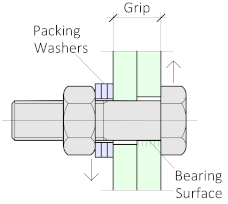
New bolt property : Do not drill filters
With this property, it is possible to have the bolt not add any holes to certain objects
This is done with the help of multiple filters that can be entered per bolt.
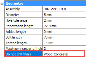
In the value field of this property, you have to enter all the filter values separated by a semicolon ;
The bolt will not create any holes in parts that match one of the values you have entered here in the following properties :
- Material
- Phase
- Remark
- Structural type
- Struct group