Bolt
The 'Bolt' object type has the following headings:
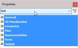
General: Is common to all object types, and covers general AutoCAD and BricsCAD settings, including: Color / Layer / Linetype / Linetype scale / Plot style / Lineweight / Transparency / Hyperlink / Handle /
3D Visualization: Is also common to all object types and includes: Material.
The material that is referred to here is only the visual representation material. For changing the actual material of parts, see the Additional Data section of plates, profiles or structures.
Geometry
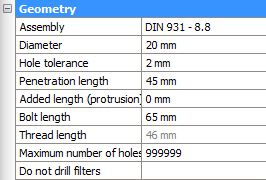
Assembly: Select a Bolt assembly from the drop-down menu. For more information refer to Bolt Assemblies
Diameter: Edits the bolt diameter
Hole tolerance: The diameter of the bolt's hole = diameter of the bolt + hole tolerance
Penetration length: This is the combination of the thickness of all the drilled part(s)
Added length: Minimum length of the bolt = net length (material length) + nut thickness + thickness of all washers + added length. This minimum length will be used to extract the actual bolt length from the part database. The actual bolt length shall be equal to, or longer than the minimum length of the bolt
Bolt length: The effective length of the bolt taken from the Bolt parts database. The length of the bolt can be changed temporarily for drilling extra holes. Method: Bolt penetrates one flange of a tube; it needs to penetrate both tube flanges. Increase the bolt length enough to pass completely through the tube. Now use the command Check for new holes on the tube and the bolt. The bolt will be given the correct length and the second hole will be drawn.
Thread length: The thread length is taken from the Bolt parts database
Maximum number of holes: You can enter a limit on the number of holes that this bolt can have. Parts will get holes starting from the bolt head until the maximum number of holes limit has been reached.
Do not drill filters - With this property, it is possible to have the bolt not add any holes to certain objects
This is done with the help of multiple filters that can be entered per bolt.
In the value field of this property, you have to enter all the filter values separated by a semicolon ;
The bolt will not create any holes in parts that match one of the values you have entered here in the following properties :
- Material
- Phase
- Remark
- Structural type
- Struct group
Misc
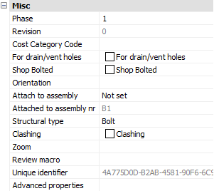
Phase: Changes the project phase of the selected element
Revision: This value is automatically assigned by Parabuild. Whenever the part is create or modified, then it will get the current revision that is currently active in the Revisions manager.
Cost category code: These codes are usually determined while a quote for the project is made. This code can then later be assigned to the 3D model when the project was ordered. This way the parts can be traced from estimation to production and to completion inside ERP/MIS software. This value is exported to KISS files.
For drain/vent holes - When this property is enabled, then all of the holes drawn by this bolt will also get this drain/vent holes property enabled. Drain/vent holes will get no dimensioning on the assembly drawings at all, contrary to regular holes.
Shop Bolted: Activating the checkbox will set the bolt to shop-bolted - See Bolts/Holes > Shop Bolts
Orientation: Clicking on the button will switch the orientation of the bolt
Attach to assembly: From the drop-down menu, select which element the bolt should be attached to. Options include 'Closest to bolt head' or 'Closest to bolt end'
Attached to assembly nr: This will indicate which assembly number the bolt is currently attached to. It is assigned automatically based on the above property.
Structural type: ** For example: Bolt or Anchor bolt **
Clashing: This is set to yes or no and refers to whether the profile is currently clashing with other elements or not. This property is automatically set by the clash control, and is only included in properties for search objectives. For more information read the chapter Clash Check
Zoom: Zoom to the extents of the selected bolt(s)
Review macro: Will open the Macro Edit dialog, where the macro that owns this bolt may be viewed and/or edited
Unique identifier: Unique identifier allocated by Parabuild, or received from a CIS/2 or Ifc file import.
Advanced properties - Clicking on this button will open the advanced properties dialog, which contains the following properties for bolts :
- Pre-classified type - This property is only useful for template drawings of connections/macros.
This setting is a good alternative way to automatically assign structural types when it is too difficult or impossible to create filters that detect the type of part automatically.
To make this work, you first have to set the pre-classified structural type here, and then save the template drawing in the library. Then the next time when the template drawing is used and inserted into the drawing, then this pre-classified structural type will be set in the structural type property of the part upon insertion.
The purpose of this is to have an influence on the automatic assignment of the structural part type property, without having to rely on the automatic Structural types assignments through Object Filters. - Only draw holes in parts that are used by the macro that draws the bolt - This option can help when bolts should be refrained from drawing too many holes.
Normally, bolts in Parabuild will automatically add holes whenever they collide with a part.
This is the design intent of Parabuild to make drawing parts fast and easy and reduce the amount of mistakes that can be made.
But in some special cases, this feature is not desired.
In this example of purlins or side rails/girts, it is the constructor's desire to have as many purlins with the same part number as possible.
This can be achieved by adding holes at pre-determined fixed locations at offset from the start and end of the purlins.
With the help of macros, these holes can be drawn automatically using helper bolts.
But when the purlins are overlapping (Z shapes), these helper bolts may inadvertently cause holes to be drawn in the overlapping purlin.
And that in turn will cause the parts to get different part numbers.
When enabling this option for the helper bolt, the macro that draws the bolts will be used to decide which purlin/rail is drilled and which one is not (the purlin/rail on which the bolt is drawn will get a hole, the others won't).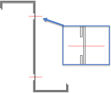
An example of helper bolts that add holes in one part, but purposefully does not add holes in the other part
Representation
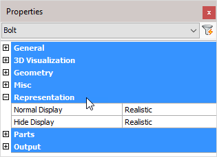
Normal Display: Selects the bolt display style in 2D wireframe
Hide Display: Selects the bolt display style in 3D Visual styles
Parts
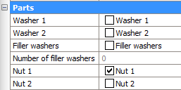
Washer 1: Enables or disables washer 1. The standards used for these parts are recorded in Bolt Assemblies
Washer 2: Enables or disables washer 2. The standards used for these parts are recorded in Bolt Assemblies
Filling washers: Enables or disables filling washers. The standards used for these parts are recorded in Bolt Assemblies
If the length of the bolt thread is not long enough (according to the standard) then it will not be possible to tighten the nut onto the work. This will also be visible in your drawing. Turning on filling washers will add sufficient washers enabling the bolt to be completely tightened
Number of filler washers - When the Filler washers (Packing washers) option of the bolt is enabled, and the shank of the bolt extends beyond the Grip (see illustration), then Parabuild will automatically add as many washers as necessary to make sure that the nut does not touch the thread runout or shank.
This property shows the number of filler washers that were applied on this bolt for this purpose.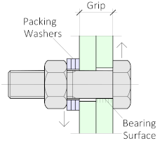
Nut 1: Enables or disables nut 1. The standards used for these parts are recorded in Bolt Assemblies
Nut 2: Enables or disables nut 2. The standards used for these parts are recorded in Bolt Assemblies
Output
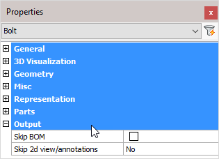
Skip BOM: If this property to ‘Yes’, this element will not appear in the BOMs
Skip 2D view/annotations: Adjust this to skip this element for the 3D annotations or the 3D annotations + 2D view
Holes
The last properties of the bolt are always the holes that the bolt may have.
All holes will be shown here separately, starting from the bolt's head the first hole will get number 1 and so on.
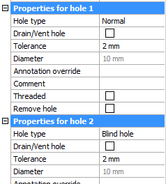
These are the properties for holes.
Hole type : Normal, Slotted, Counter sunk or Blind. For more information about the hole types, see their respective topics.
Drain/Vent hole : All the holes that are designated as 'drain / vent' holes will not receive any dimensions on the assembly shop drawings.
Tolerance : The tolerance for the hole in relation with the bolt.
Diameter : This value is only informative because it is derived from the bolt diameter and the tolerance.
Annotation override : When you enter a text in this field, this text will always be shown in the annotation of this hole on the position shop drawing. It will override the default text which would be the diameter, slotted, countersunk and thread information if it is such a hole type.
Comment : Feel free to use this field to add comment to the hole. It will only have an effect if the variable %PbColHoleComment% is used in an annotation or in a parts list.
Threaded : See the threaded hole topic for more info about this.
Remove hole : This is an action. Clicking on the button will erase this hole.