
Version 9.1 - Migration guide for users
Summary
These are the most important changes and additions in this release :
- Previous selections offers access to a previous selection instantly, outside or from inside any command. This avoids you having to select the same objects twice.
- Previous filter actions allows us to redo a filter action that was done before, without having to re-enter the information again.
- The expanded Sheet changes tracking after changes to the 3D model will now also tell you which sheets need BOM changes and thus should be pulled from the workshop. This tool can help when workshop drawings have been issued to the workshop, production has started, but changes need to be done to the 3D model and you need to know which sheets issues to the shop should be retracted or modified.
- Ifc export property sets allow us to attach any property to any part when exporting Ifc files
- Export each part or assembly as a dwg file containing 3D solids was added for certain CNC processors that require it, or for other file exchanges
- A set of new connections and macros were recently added to the library
- Access part information from within macros and cross-macro information retrieval, for power users that make customized templates
- Various other new options and settings
Previous selections and Previous filter actions
This tool gives you access to the last object selections that you did, or the last filter actions that you did.
You can use this when several commands need to be done on the same objects, or, more importantly, when you cancelled or undid a command because of a mistake.
You will have access to that previous selection or action instantly, outside or from inside any command.
The new features Previous selection as well as Previous filter actions were added to the Quick select dialog box : 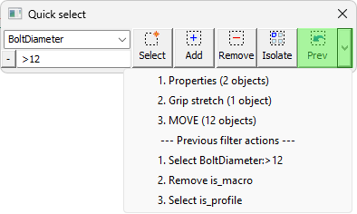
Clicking on the Prev button will directly select the objects that you selected during the last command or property change.
Clicking on the drop-down button allows you to see and restore the last 10 previous selections and the last 10 filter actions.
What we're seeing in the drop-down menu are 2 distinct features, each is explained below :
Previous selections
Any command that you use that asks for the selection of 1 or more objects will be stored in this list.
This includes all Parabuild commands but also all AutoCAD/BricsCAD commands such as move, copy, mirror.
The last selection that you made is shown at the top of the list so the oldest selections will disappear when there are more than 10 previous selections.
There are certain other selections that you may do outside of commands, such as when you select objects and then do a properties change on them.
These changes in properties panel are also recorded as previous selections, the modified objects are stored as a previous selection.
Previous filter actions
Filter actions are recorded each time that you click on one of the 4 quick select buttons : 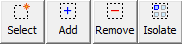
Each click that you do here will cause the action to be added to the previous actions, with a description of the type of filtering, the name, and value on which was filtered.
A big difference with previous selections is that here the selected objects are not stored but rather the filter action itself with it's filter value.
When you click on a previous filter action the entire drawing or the current selection will be queried for objects to select or deselect, so it repeats the same filtering action without having to set the filter name and value again.
Sheet changes tracking after changes to the 3D model
The Check sheets validity tool was expanded and will now also tell you which sheets need bill changes and thus should be pulled from the workshop.
It will show new information that looks like this :
Sheet 'Parts\Plates\12\PL1' has outdated bill table(s). The following rows and columns do not match with the 3D model anymore:
Bill 'Position list' : Cell 'Tot' on row 1 is now '2' (instead of '1')
This tool will help you when you are in the worst kind of revision situation : Workshop drawings have been issued to the workshop, production has started, but changes need to be done to the 3D model.
All the missing sheets, expired sheets, and sheets with wrong amounts are listed by the validity checker. This list tells you which sheets to pull from the workshop and that need to be refreshed or removed entirely, and which new parts or assemblies need a new sheet.
How it works
The check sheets validity tool is to be used right after doing the revising changes to the 3D model, but before refreshing the sheets. It can be used before or after numbering and it will work in both cases. However doing it after numbering will give you a better result because it will show you the new correct amount of parts for each sheet. If you did not number, then some parts may still be without a number and will not be assigned to any sheet (you'll be warned of this separately).
It compares the 3D model to the existing sheets and does no changes to the sheets except for assigning expired views when detected.
The current bills on the sheet will be checked to verify they are up-to-date, without being updated which would be done when refreshing the sheets.
Currently this tool covers the issue of finding out which workshop drawings need to change when they have already been sent to the shop. A likewise solution for GA sheets will be added to a future release.
Note It is possible that a part or assembly has changed, but that numbering restores its original part/assembly number. The changed geometry is still detected and causes the view/sheet to be expired, which is the intended result. As a consequence of the expired sheet, this tool will say that the amount of parts on the bill has reduced to 0. But when you refresh the sheet afterwards, it will reconnect the sheet to the same part/assembly number and the bill will then correctly show the new amount of parts/assemblies.
The new tool will be most helpful by warning you about the quantity changes on a sheet, but this will also detect changes to all other cells in the table such as names, materials and finishing.
Use this tool after applying changes to the 3D model but before refreshing the sheets.
After refreshing the sheets, the information about the differences between the 3D model and the sheets are lost, as they are now in sync.
Ifc export property sets
Parabuild now allows you to attach any property to any part when exporting Ifc files.
This will allow you to better comply to the Ifc data requirements as set out by the main contractor of the project.
The property sets as they are defined by the used standard (for example BIM Base IDS or BIMids) can be defined with these property sets in Parabuild.
The chosen properties will apply to the Ifc file of the entire project as well as the individual per-part and per-assembly Ifc files.
See the topic Ifc Export Property Sets for more information on how to use this feature.
Export each part or assembly as a dwg file containing 3D solids
This can be used for CNC processing or other file exchanges.
This feature can also add the sheet of the part or assembly to the dwg file.
In that use case, the dwg files could be opened on a tablet or mobile to review the 3D model of that part or assembly together with it's sheet.
You can export these dwg files with the Export BIM to file command.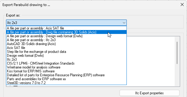
New connections added and changes to existing connections
The following macros were recently added or changed in the library :
Truss macros were changed
Command - (Prb_MacroGroup "Vakwerk")
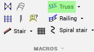
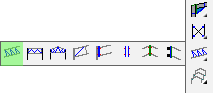
All the truss macros were changed to allowing for a new offset distance between each strut.
New Misc ending connections
Command - (Prb_MacroGroup "Misc end connections")
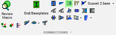
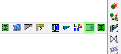
The new connections are explained here :
|
Side plate |
This macro draws a Side plate against a wooden purlin or girt, towards a planar surface, allowing you to use this macro against any plate or profile with any section type |

New endplate/footing connections
Command - (Prb_MacroGroup "Voetplaten")
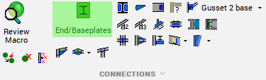
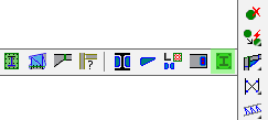
The new connections are explained in detail :
|
Corner endplate for tubes |
This macro draws an endplate with a corner cut off from it. Both extending sides can have bolts in them configured separately. |

New connections for CNC lasered tubes
Command - (Prb_MacroGroup "Weld connections")
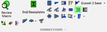
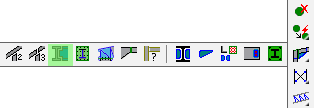
These new connections were created specifically for rectangular tubes and pipes that will be produced with a CNC laser.
Some of them will have inserts in the tubes so that they will fit instantly. They are perfect for assembling and welding in the shop without the need to measure and no mistakes can be made!
The new connections are explained here :
|
Half on Half |
This connection is for 2 rectangular tubes that intersect each other. They will both be cut open halfway to make them fit perfectly on each other. The tube that you select first will get it's top half cut away, the secondly selected tube will get it's bottom half cut away. The connection will also work in inclined situations. |
|
Pipe miter with inserts |
This connection draws a miter to connect the pipes, but it also adds inserts to the tube that was selected first so that it can fit in the same-sized holes in the other pipe. The angle at which the pipes arrive does not matter. The same connection existed already before but for rectangular tubes only. |


New Bracing macro
Command - PrB_Bracing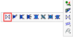
The new macro is explained here :
|
Channels 2 interrupted |
This new bracing macro will draw 4 channels in total, all interrupted in the center. |

New gusset plate connections for channels
Command - (Prb_MacroGroup "Schetsplaat 2 basis")
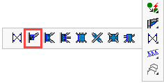
The new connections are explained here :
|
Small Pentagon gusset plate |
This macro existed already but was added for channel bracings, with the modification to allow multiple rows of bolts to be drawn |
|
Bottom Pentagon gusset plate |
This macro existed already but was added for channel bracings, with the modification to allow multiple rows of bolts to be drawn |


Bracing center plate connection changed and added
Command - (Prb_MacroGroup "Centerplaat 4 basis")
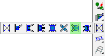
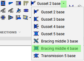
The changes are explained here :
|
Center plate |
This connection was modified to allow for optional chamfers on each corner of the plate. And a variant has been added so that it will also work on a bracing of 4 channels |

New Purlin/Girt connections
Command - (Prb_MacroGroup "Gordinghaken")
The new connections are explained in detail :
|
|
This macro draws a side plate for a wooden purlin or girt. |
|
Stiffener for Sigma |
This macro adds a stiffener-like plate inside an I-beam, and the plate extends to the Sigma profile so that it can be bolted against it's back |


Access part information from within macros, for power users
For power users that develop their own macros, a new set of features have been added that again add a big set of capabilities :
- We can access part information directly from within the module. A practical example of this is finding out whether a part is clashing or disabled, and responding to this by for example disabling the module, or any other macro behaviour that you can envision. The macro variable retrieves the information from the part, and your equation reacts to that information.
- We can now access variable values of other macros directly from within the module.
Both of these features make use of the part name which can be set on the Geometries tab : 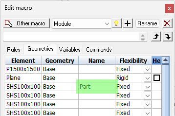
Example of retrieving filter/property information from a part
The name of the part or object that was entered in the Geometries tab can be used in variable names like this : 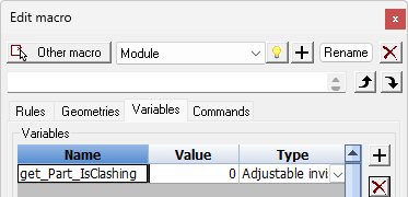
The syntax is get_PartName_PropertyName
- get_ signifies that Parabuild should try to retrieve this variable's value automatically based on the remainder of the variable name
- PartName is the name of the object from which you want to retrieve a property or filter. This name needs to be assigned on the Geometries tab.
- PropertyName is the name of the property or filter itself, and this could for example be IsClashing to get the clashing status of the part or IsContructionGeom to get whether the part was hidden inside a macro or not, or any other numeric object property.
This will work on all available filters and properties in Parabuild that return a boolean, integer, or double values but not strings.
This will work also on custom filters that you created, but in such case watch out with different installations : when the Parabuild library and the filters file in it is not copied to another installation then the macro will respond differently (the variable will not change on that other installation).
You can search for properties and queries among the Parabuild default Properties and queries or inside the Quick select dialog box which contains a more complete list that includes locally defined filters.
Example of retrieving a variable value from another macro
Such a variable could look like this :
get_PartName_Owner_ModuleName_VarName
This is the meaning of each section of the string :
- get_ signifies that Parabuild should try to retrieve this variable's value automatically based on the remainder of the variable name
- PartName : is the name of the object from which you want to retrieve a property or filter. This name needs to be assigned on the Geometries tab.
- Owner : This is a fixed word that we add so that Parabuild knows that it needs to find the owning macro of PartName
- ModuleName : This is the module name that Parabuild should find inside the owning macro. If the variable is located in the module that owns the part then you can omit this module name from the string
- VarName : This is the variable name that Parabuild should retrieve in the owning macro and module
As you can see, this feature relies on geometric dependencies to find the other macro to retrieve the variable from.
And as a consequence, we can only retrieve macro values from macros that the current macro depends on, not the other way around.
If the object is not owned by any macro (or the owning macro was deleted later on), then the variable in your module will be left untouched as is.
We are limited by the variable names for these features.
Therefore you should not use spaces, underscores, or any mathematical signs in object names, module names or filter names. In those cases this feature will usually not work.
Various other new options and settings
- A behavioural change has been applied to the double-click on parts :
When you double-click on an edge of a hole or cut, then the macro that owns that cut or hole will be opened for review.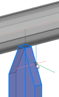
All you have to do is move the cursor's small rectangle over an edge of the cut or hole as shown below, then double-click.
This macro is not always the same macro that owns the part itself, which is why the new behaviour was added.
This double-click method will work in all visual styles, except if other objects are in front of the cut. Only the 2D or 3D wireframe visual styles can handle such a double-click case because all other visual styles, even X-Ray, will often draw faces in front of the edge that you double-click, and that makes the edge-detection fail.
The macro spheres do not need to be visible if you want to review macros. The double-click is a practical tool to review macros even when all spheres are invisible. - The Quick select tool has a new filter action called <Macros that own cuts or holes in the objects> :
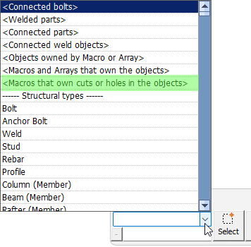
This allows for example to add the macros to the selection when you are copying a plate or a profile.
It may be a challenge to know which macro owns the cuts or holes when there are many macros close to each other.
Moreover, the macros may have been hidden, and this selection tool will select or deselect them anyway.
Note that copying macros will only work well if you are also selecting all of the parts that are owned by the macro and all of the base geometries of the macro (the column for a baseplate). Failure to do so will result in a broken macro and you might as well just not copy it in that case. - A behavioural change has been applied to dimensions that are manually drawn on 2D sheets using the Chain Dimension, Ordinate Dimension , and Chain + Ordinate Dimension commands :
When the current layer is set to 0 then the new dimensions will be set on the Pb_TracWorkshopDims layer so that they get the same colour as automatically drawn dimensions.
But when the current layer is set to a layer other than 0, then the new dimensions will get the current layer. This gives the drafter more control to use colouring schemes when manually drafting dimensions.
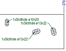
- A new option was added to the automatic dimensioning which allows us to configure how slot holes should be dimensioned :
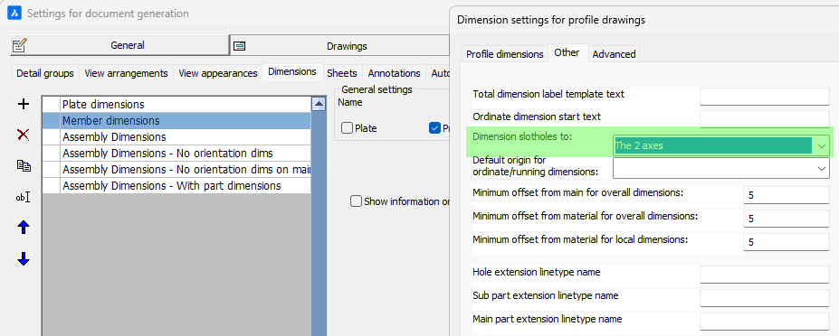
The new setting has the following options : - None - This will not draw any dimension for slotholes :
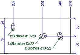
- Center - This will only draw dimensions for the center of each slothole :
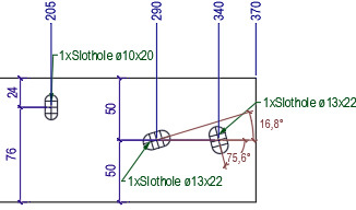
- Center and angle - This will draw dimensions for the center of each slothole and an angle dimension for each slothole that is not parallel or perpendicular to the part's main sides :
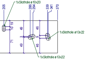
- The 2 axes - This is the default and it will draw dimensions for the axes of both radii of the slotholes :
- The following new global settings were added:
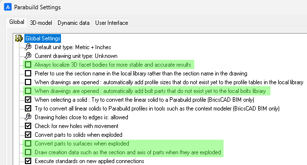
- Always localize 3D facet bodies - Enable this to increase stability and accuracy of complex bodies with many faces (and curved surfaces). The localization is being done in the background and has no influence on the resulting 3D model. This setting is in our experience helpful in BricsCAD.
- When drawings are opened : automatically add bolt parts to the local bolts library - When enabled this allows Parabuild to auto-add bolt parts to the library from drawings that are opened.
This should improve consistency in drawings when a computer has missing parts (eg a drafter using a different machine added new ones).
This will not modify parts that are already in the library.
Bolt parts are stored in one of the files in this library folder :
for metric : \Pb_Lib\Bolts\Parts Metric\
for imperial : \Pb_Lib\Bolts\Parts Imperial\
There are several files in this folder that allows us to group the parts and avoid file collisions when the library is updated.
The unknown parts that are encountered in drawings are stored into the same filename as the origin system if that filename exists already.
If this filename does not exist yet then the bolt parts will be added to the file named "Auto Added Parts.dat". - Convert parts to surfaces when exploded and Draw creation data when exploded - These 2 new explode options plus the older one allow us to draw more objects when Parabuild parts are exploded.
All of the 3 options concerning exploding can be combined freely. The resulting objects after explode will be drawn on top of each other if multiple are activated.