Steel Detailing in 3D
Efficiently modeling 3D steel structures
Our ultimate goal is to make steel detailers, engineers and fabricators as productive as possible. Therefore the ideal structural software should be intuitive, user friendly, efficient and flexible.
Because steel detailing involves a lot of parts, we have made sure modeling is a fast and straightforward process.
Powerful connection and macro system
The first unique way this is addressed in Parabuild is the powerful connection and macro system. Not only is the expansive standard connection library convenient and easy to use, every single one is created using tools that are available to all drafters without requiring the programming of a single line of code. Every standard or user connection resides in a template drawing which means the detailer can adapt it to his own needs. Parabuild is the only structural steel detailing software that allows the user to define any type of connection without programming. Newly made connections are entirely integrated with the existing connection system for easy re-use in all your projects. Macros are built up in the same template-based way as connections and can compose of any number of members, connections, dynamic arrays and sub-macros. Examples of provided standard macros are bracing, trusses, purlins, cage ladders, etc…
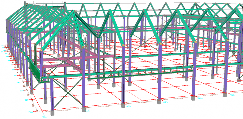
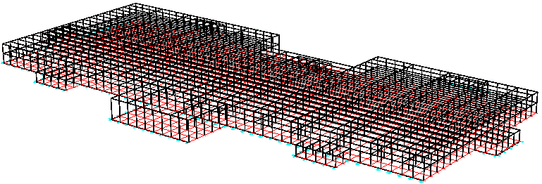
Fast and easy 3D modeling
The second powerful modeling method in Parabuild is the Context Modeler, a new tool to help you draw and detail your structure easily and rapidly. No building is completely standard, so no amount of standard macros and connections will ever suffice to meet all your needs. Designed specifically for the construction industry, the Context Modeler helps to rapidly and accurately draw frame elements and sub-parts, all linked to eachother and responsive to changes.
The interface could not be more self explanatory: tell Parabuild what you need in simple terms, and point to the location where you need it. Parabuild will show a temporary element dependent on the cursor location and the construction elements near the cursor. Move around the cursor and different solutions are proposed, with magnet-like snapping to edges or middle points. The result is new geometry that was automatically linked with base geometries using geometric constraints. The big advantage is that you can model directly in 3D without cumbersome intermediate steps, and still end up with a completely linked model.
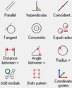
Geometric constraints
The driving force behind the simple but powerful interface are geometric constraints. While this is automated in Parabuild, all geometries are linked with each other using simple geometric rules (parallel, distance, …) and calculated by the geometric solver. This allows for the re-use of connection and macros, and makes your drawings are easier to update when changes are needed.