Context Modeler
Fast and easy structural modeling
When standard library macros and connections are not sufficient to finish the structure it is important not only to be able to create and position geometries quickly and easily, but those geometries should also be easy to modify and should respond to changes in linked geometries.
To meet this requirement we designed the Context Modeler, an interface that communicates with the user in the most natural way, in other words an interface that was inspired by the way people communicate with each other: offer some basic context and point to the desired location.
Fast frame modeling
For adding individual structural elements such as beams, columns, girders, struts, joists, and purlins, use the Context Modeler for maximum productivity. Move the cursor around and Parabuild proposes sensible solutions based on cursor location, available members and additional available context. Tell the software what you need and point to the location you need it and the new frame element is automatically constrained to the grid, connecting members or frame lines.
Intuitive interface
The user interface could not be more self explanatory: tell Parabuild what you need by clicking images that resemble what you need, and point to the general location where you need it. Parabuild will draw a temporary element dependent on the cursor location and the construction elements near the cursor. Move around the cursor and different solutions are proposed, with magnet-like snapping to edges or middle points.
Automatically linked geometries
The result is new geometry that was automatically linked with base geometries using geometric constraints. Afterwards you can still change dimension values or choose other reference geometries when desired.
Fast assembly modeling
For those times when the standard connections and macros are insufficient, create parts with minimal effort using the Context Modeler. After selecting the part type move the cursor across the model and Parabuild proposes part placements relevant to that location and context in real time. The new part is automatically linked to the relevant member(s) or parts and will update when those change. All of this means you can draw most parts without changing the view or UCS and with a minimum of clicks, and still end with a more powerful, intelligent 3D model.
Responsive 3D model
The grid, structural frame, connections, parts and bolts are all linked up and adapt when needed. When the grid is changed, the frame will adapt and when the frame changes the connections will adapt. This results not only in productivity gains during revisions, but presents opportunities for re-using some regularly drawn building components.
In-place editing
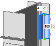
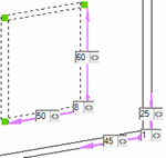
When using the Context Modeler, click on a part to show all of the dimensions that determine it’s location and size. No dialog box, but directly on your 3D drawing. Drag the dimensions to change the size. Click a reference button to change the reference part(s).
Easy rotations
If the orientation proposed by the Context Modeler is not the one you need, use the keyboard arrows or on-screen buttons to flip to the next valid orientation that satisfies the given input. No need to enter angles or reference points!
Simple contextual input
Tell the Context Modeler what you need through simple types such as beam, column, stiffener, endplate and also concepts such as plate/axis/grid alignments or inside/outside a member profile. Need to place an element on the back side of a member? No need to switch the view or UCS, just click the ‘Back Side’ context button and the Context Modeler will take care of it. Providing contexts like this helps narrowing down the options and getting to the finished geometry faster.


