Geometric Constraints
When detailing a building many connections and parts will be repetitive, and often changes will be needed to the model. Therefore it is important that your structural detailing solution offers a 3D model where the grid, members, parts and bolts are all linked and adapt to changes.
The obvious choice to implement this is geometric constraints, a solution that has been very successful in mechanical CAD but never got adopted in steel detailing. The reason for this is also obvious: there are thousands of geometries in a single structure and it would be too much work for a detailer to manually constrain all of them. Another challenge is for the software itself: calculating large constrained models like this takes a long time on mechanical CAD software.
With Parabuild we introduce new technology to meet these challenges. The performance problem has been solved by writing a proprietary geometric solver designed specifically for the structural sector. Manual constraining is only needed for detailers that wish to create custom connections and macros. Templates can be applied with ease in any 3D model, and Parabuild will take care of copying the constraints. Members and individual parts can be efficiently placed through the Context Modeler and will be automatically constrained.
What are geometric constraints
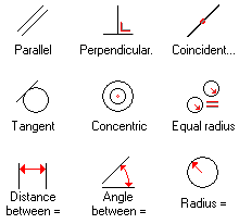
Constraints are rules that can be applied to geometries to define their size, location and orientation. It can be useful to think of them as restrictions; once enough restrictions are applied to a geometry its location and size is fully defined and can be calculated by the geometric solver. Some examples are: distance, radius, parallel, perpendicular, concentric, coincident, …
Equation system
When your custom connection or macro is a little more complicated, use equations to your advantage. Combine standard operations (multiplication, divisions, additions, …), standard functions (round, log, abs, …) with trigonometry (sin, cos, tan, …) to automate your calculations. Equations can also be conditional through switch statements.
Constraints are optional
In some cases you might just want to draw members or parts without having them linked up. This is perfectly acceptable and a 3D model can be mixed constrained/not constrained. For example: two unconstrained members can still have a constrained connection or macro between them, and the connection or macro will update when the members change.
Responsive 3D model
The grid, frame, connections, parts and bolts are all linked up and adapt when needed. When the grid is changed, the frame will adapt and when the frame changes the connections will adapt. This results not only in productivity gains during revisions, but presents opportunities for re-using some regularly drawn building components.
Customization without programming
The standard connections and macros in Parabuild are all fully defined using geometric constraints in template drawings. This means it is possible to modify existing connections or add any new custom connection without hiring a programmer or writing any code.
Powerful connection and macro system
To maximize modeling efficiency connections are constrained inside template drawings, so they can be re-used in the 3D building model just by clicking the members to be connected. Standard connection templates are provided, but any drafter can make their own. Every template is created using tools that are available to all detailers without requiring the programming of a single line of code. Macros work the same way and can involve multiple connections, arrays and members. Examples of provided standard macros are bracing, trusses, purlins, cage ladders, etc…
More details about connections
More details about macros
Context Modeler
Designed specifically for the construction industry, the Context Modeler helps rapidly and accurately drawing frame elements that are automatically constrained to the grid and to each other. It can also draw sub-parts that will be automatically constrained to members or to other parts. The result is new geometry that was automatically linked with base geometries using geometric constraints, so you end up with a linked model that is responsive to changes in the design. The big advantage is that you can model directly in 3D without cumbersome intermediate steps, and still end up with a completely linked model.


