Parabuild version 3 is now available and introduces an entirely new method for drawing structural objects in 3D : “Context Modeling”.
These are some of the new features in this new release :
Context modeler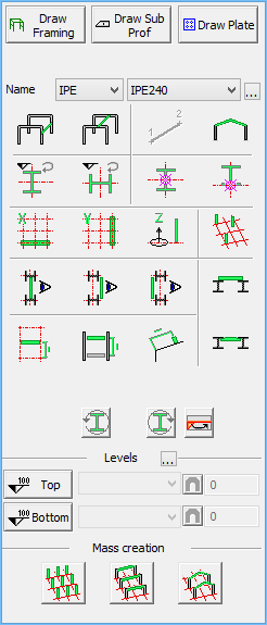
Parabuild introduces a new way of working : context modeling!
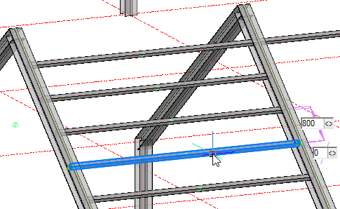
When you are drawing a new element, Parabuild will continuously offer new proposals depending on the available geometries close to the cursor.
The result is influenced further by clicking on the ‘context’ buttons: simple ideas that can define geometry location, rotation and linking.
Our eventual goal is to make drawing in 3D incredibly simple : you describe what you want to draw, point to the desired location and click to confirm! So gone with excessive switching of work planes and changing views, and gone with endless move and rotate operations!
Aside from drawing smaller parts based on a bigger member, you can also draw the frame structure itself with the context modeler.
You can draw columns that are automatically linked to the grid lines. Beams are automatically linked to 2 base profiles.
If you choose to link columns and beams to a level, then they will adapt when the level changes.
A short example: by moving the cursor between 2 columns Parabuild proposes a beam on screen. If this is not the beam you want, then you can change the proposal with a few clicks. For example you can choose:
- Only between columns or only between beams.
- Centered between base profiles, or on top / next to them.
- Parallel with X or Y, or also flat or straight up
- Specify an offset distance to a certain level
All elements that you draw with the context modeler are automatically defined using geometric rules. The result is that these elements can be edited very efficiently and will also adapt after changes to the structure.
 In-place editing
The parts that you draw using the Context Modeler are automatically defined using geometric rules.
Select the part and you can immediately modify all parameters on screen, without having to open a new window.
View manager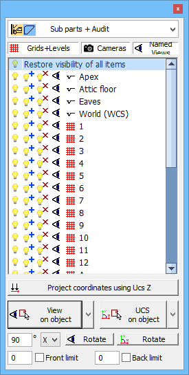
Using the new view manager you can quickly change views, modify the view
limitation or change UCS based on one of the grid lines or levels in the drawing.
An even more important tool in view manager is the possibility to make a range of elements visible or invisible with just one click. This is possible based on the grid lines, the levels and the cameras. Therefore you will not need to change the view that often anymore, because you can hide the objects that are obstructing the view instantly.
Color styles
Another new tool in view manager is the color styles.
You can choose between 4 color styles : Assemblies + Audit, Only assemblies, Only audit or Layers based.
You can choose the color style you want, and this color style stays active across all visual styles. This makes it possible to draw more easily in visual styles such as X-Ray.
Even more is possible with the view manager, such as :
- Setting View or Ucs along a grid line or level
- Setting the Ucs on a plane of an object
- Project all Osnap Z coordinates to 0 on the Ucs
- Various view manipulations
- Extended Ucs manipulations
Exercises to get you started quickly
When you start Parabuild v3 for the first time you will see a dialog box that contains all available exercises.
These exercises are designed to make it fun to learn Parabuild. Try it out now in the free trial!
The exercises are meant for both new and existing users : the new features in version 3 are also covered.
Parabuild Viewer / model checker
Each new Parabuild installation without a license will function as a viewer.
You can open drawings with it, but also see properties of Parabuild objects and check the parameter values of connections. You can also draw AutoCAD/BricsCAD objects or add comments, and then still save the drawing. The Parabuild viewer can be freely distributed among your company or other companies!