Version 9.0 - Migration guide for users
Summary
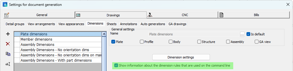
These are the most important changes and additions in this release :
- Sheet refresh was completely rebuilt and has become easy to use and powerful now especially for shop drawings. Dimensions and annotations connected to views will be automatically be adapted to the changed geometry only when needed. Dimension updates are done as conservatively as possible to preserve the drafter's intent. The new sheet refresh makes updating shop and general arrangement drawings after model changes much easier and faster.
|
|
|
|
A shop drawing before refreshing |
A shop drawing after refreshing |
- Further performance improvements for projects with thousands of sheets: sheet manager performance was greatly improved for many actions and responds quickly when opening drawings or switching sheets. Together with the improved sheet refresh this makes large projects in a single drawing much easier to handle in Parabuild.
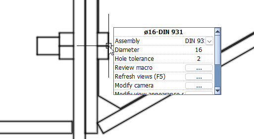
- The new Context menu tool gives you relevant properties and actions for the object under the cursor. An example is to change the diameter of a bolt in the 3D model or on a view without having to search for an icon or a property first. The list of available properties and actions can be customized.
- We are introducing a new Programming API (Lisp and C++) for advanced customization of Parabuild
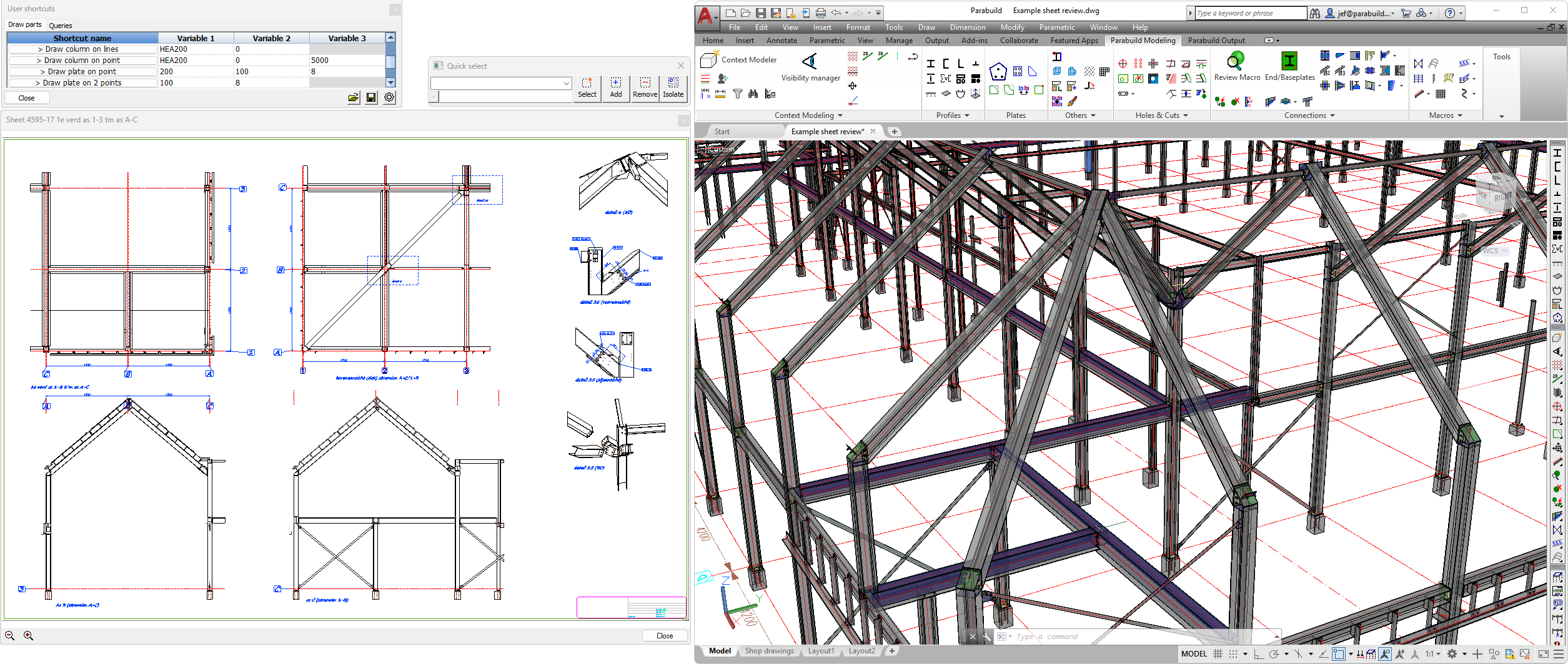
- The new User shortcuts is a tool that facilitates customization by reducing the amount of code and knowledge needed to add small automating functions for Parabuild. It offers an easy start to the new Parabuild programming API. It provides a quick way to further automate repetitive actions specific to your workflows, without the hassle of entering commands or creating dialog boxes or menu buttons.
- Complex bolt parts allow us to display complex geometry to represent hold down clips, bevel washers, cap nuts, nylon plugs, and any other parts that can be drawn with extrusions and/or revolutions. These parts can be drawn as a part of bolt assemblies, making them more efficient to model and more lightweight in terms of computer resources.
- Reviewing sheets can now be done in a separate dialog so that two sheets in the same drawing can be compared, or the 3D model can be open at the same time as 2D sheets of the same drawing.
- Export the 3D model and paper spaces to a Dwfx file including object properties for sharing and reviewing in Autodesk Design review or other viewers.
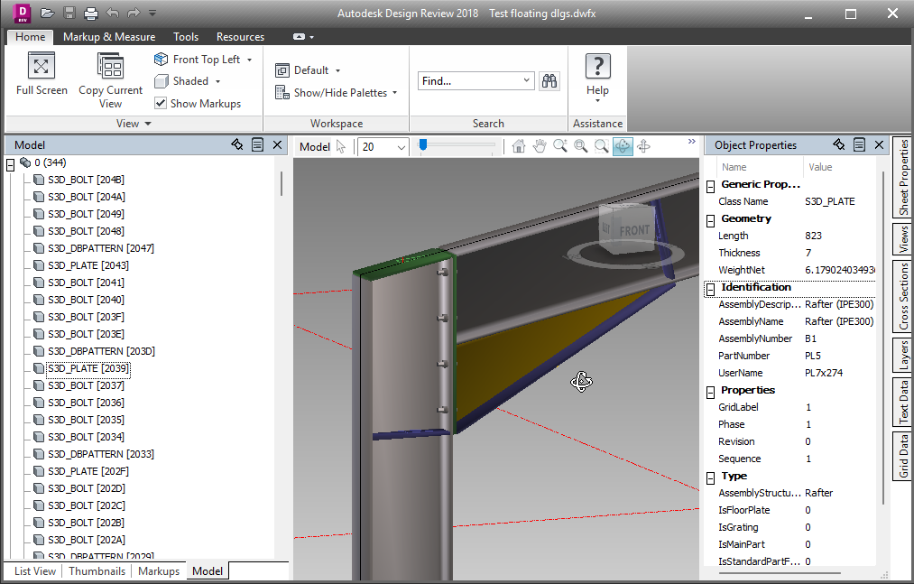
This is a Dwfx file being reviewed in Autodesk Design review, with object properties - Export individual files per part or per assembly (Ifc, Dwfx, or SAT) to distribute along with shop drawings and CNC files, or for importing into ERP or cloud solutions
- Export multiple sheets into a single pdf file. This also supports combining a mix of format sizes into a single Pdf file.
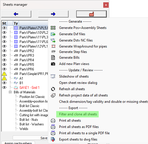
- Filter and clone sheets allows you to make copies of a certain sub-selection of sheets such as a particular phase. The cloned sheets will contain the correct amount of parts for the filter that you chose, and sheets without parts that passed the filter will be skipped. This allows for workflows with fewer sheets to create and clean up, and only generating the filtered clones when needed.
- Automatically apply sheet filters when printing or exporting sheets. Similarly to filter and clone sheets, but this command sends the filtered sheets straight to the printer (paper or PDF).
- The new Check sheets validity tool will search for mistakes such as 2 sheets for the same part, missing sheets, outdated sheets, or unconnected dimensions. This will help prevent over-production, under-production, or the production of wrong parts.
- It is now possible to easily save connection values as defaults that will be loaded when the same connection is applied to the same size members in the future.
- A new option for newly created connections to automatically load connection values from another connection in the model if it is of the same type and based on the same size members.
- Ifc file import improvements : Parabuild can now also import non-construction geometry such as ducts and furniture as generic objects.
- Support for BricsCAD V26 was added
- And many other new smaller features
General notes about this update
- This version of Parabuild is now compatible with BricsCAD V26.
Use the Parabuild Startup settings tool to switch between CAD platforms. This tool can be found in the start menu of Windows. - The oldest supported AutoCAD version is now AutoCAD 2017. Support for older releases was removed.
The oldest supported BricsCAD version is still BricsCAD V18. - AutoCAD properties changes
In this update several new properties for Parabuild objects have been added.
To make sure that they work well on your installation, it is advised to start Parabuild as administrator the first time after installing this update
|
|
|
Parabuild can be run as Administrator by right-clicking on the Parabuild shortcut |

This will register the new Parabuild properties into the AutoCAD installation.
For BricsCAD this is not required because it has a different properties system.
This is only required after installing the version 9 upgrade. This is not necessary for new installations of version 9.
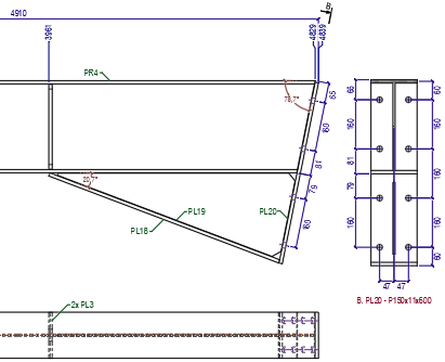
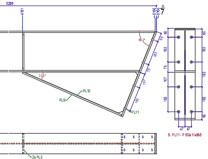
Refreshing sheets improvements
Sheet refresh was completely rebuilt and has become easy to use and powerful now especially for shop drawings. Dimensions and annotations connected to views will be automatically be adapted to the changed geometry only when needed. Dimension updates are done as conservatively as possible to preserve the drafter's intent. The new sheet refresh makes updating shop and general arrangement drawings after model changes much easier and faster.
The slope of dimensions will now also be automatically adjusted when the rotation of the dimensioned geometry has changed. Similarly, the location of part-linked section cameras such as for endplates will be automatically recalculated.
|
|
|
|
A shop drawing before refreshing |
A shop drawing after refreshing |
Shortened part and assembly views that were originally shortened as a group will also be shortened as a group during refresh, if their respective shortening settings are still consistent with each other.
There is extensive support for shop drawings made in older versions as well, especially if the sheets are refreshed before extensive model changes are done. This was tested with sheets from v7 and above.
Another new option is to automatically copy sheets during refresh when a part or assembly number has changed and split into 2 or more different parts/assemblies with different numbers. These copies will each be updated for their respective new geometries.
After refresh there is an audit that checks for unconnected annotations and dimensions, parts and assemblies that have double sheets or are missing from the shop drawings.
Refreshing existing sheets is faster than deleting and regenerating shop drawings from scratch, both for the computer and the drafter, but the main use for refresh is to preserve any manual cleanup or dimension changes done to the sheets. Revisions to the model will now become much easier to handle.
Note that when you want to refresh sheets that were generated with an older version of Parabuild, then before making model changes it is best to first refresh the old sheets with these 2 settings deactivated to force a full refresh and update all views to the current version :
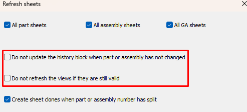
And after this first refresh you can start applying changes to the 3D model. This ensures that the sheets are now as good as version 9 sheets and refreshes after that will occur with full functionality of version 9. If this refresh is not done in advance of model changes, future sheet refresh may not be able to update all sheets if the model changes are extensive.
Notes and tips for refreshing sheets
- There is a new filter to find wrong dimensions/labels quickly in Quick select : IsInvalidDimOrLabel
- Parabuild may prefix sheets with "(REVIEW)". This usually happens when none of the views on the sheets could be updated (and all were set to outdated).
For these kinds of sheets, first check if that part/assembly number still exists.
One situation may be that two different numbers became merged number with more occurrences, so one sheet got higher counts and the other sheet became redundant.
Or some parts may have been removed from the model altogether.
For pre-v9 sheets, it may also be possible that a sheet could not be linked to it's source part or assembly because it has gone through too large changes for Parabuild's automatic detection to work. Starting from v9, these links are stored in the drawing. - Parabuild does not yet automatically create new dimensions for new geometries in the part/assembly during refresh
- Parabuild does not yet automatically remove annotations/dimensions/extensions for removed geometries of parts/assemblies.
- Views of deleted parts/assemblies will be set to outdated/invalid, and the sheet will be tagged with

- Dimensions that are not connected to view geometry will not be automatically adapted (dimension will be set to invalid and the sheet will be tagged with ), make sure to work with osnap when adding dimensions o avoid this.
- Before refreshing older shop drawings remember to set your sheet naming templates first in general settings, because refresh will fill the sheet name template field from settings if it is empty
Sheet manager performance improvements
Sheet manager performance was greatly improved for many actions and responds quickly when opening drawings or switching sheets. Together with the improved sheet refresh this makes large projects in a single drawing much easier to work with in Parabuild.
These improvements allow very large projects to be contained in a single drawing, with thousands of shop and GA drawings contained in the same file.
If you work on large projects then it will be worthwhile for you to look at the Performance optimisations topic for the best graphics performance.
New context menu tool
The new Context menu tool gives you relevant properties and actions for the object under the cursor. An example is to change the diameter of a bolt in the 3D model or on a view without having to search for an icon or a property first. The list of available properties and actions can be customized.
To use this new feature you just have to move the cursor over an object and wait for half a second. The menu will then pop up next to your cursor and will display some properties most relative to the object or sub-object underneath the cursor.
You will have the opportunity to change a property or start one of the actions in the menu directly.
The contents of the menu strongly depends on the (sub-)object that is located under the cursor, for example :
- For a line you will see the layer and color properties only
- For a member you will see profile-specific properties such as the section name and part numbers, but also the layer and color
- For a cut's edge we will see the option to delete the cut together with the other properties of the object
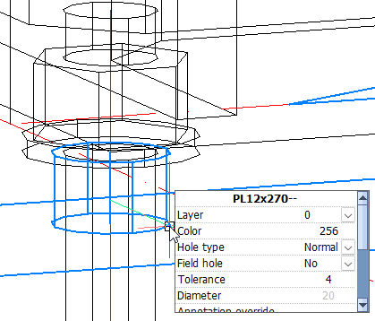
- For a hole we will see the hole's diameter and type. However since holes are usually hidden behind other objects this feature works best in 2D wireframe or 3D wireframe.
- When there is a face directly under the cursor, you will also see the action to set the ucs on that face together with the properties of the object
- For the box of a camera in a view, you will see the camera properties as will as some view properties
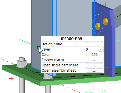
- When you move the cursor over a bolt in a 2D view we can change the diameter, open the macro that owns the bolt, or open the shop drawing of a part, all from within a sheet.
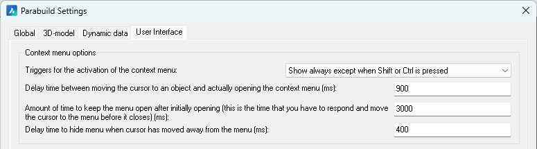
Currently the context menu is enabled by default after installing version 9.
You can disable the menu or change its behavior in the Parabuild global settings.
For example if you find that the context menu opens up too often, you could increase the open delay time or choose the shift key as a trigger that needs to be pressed before the context menu opens :
To change the contents of the Context menu, see the User Interface topic.
Programming API (Lisp and C++)
We are introducing a new programming API for advanced customization of Parabuild.
The functions that make User shortcuts work are also exposed with this API.
For now, only the Lisp and the C++ programming languages are supported.
For use in your Lisp/VLX functions just call the appropriate API functions, they are automatically registered when Parabuild is loaded.
To use this API in your ObjectARX/ ObjectBRX project simply include the header file \Parabuild\Api\PbApi.h into a .cpp file of your ObjectARX or BRX project.
There is no need to link to a library file.
This header file also includes information on how to use each function.
Read more about the exposed functions in this API help topic.
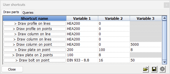
User shortcuts
Command name : PrB_UserShortcuts
The new User shortcuts is a tool that facilitates customization by reducing the amount of code and knowledge needed to add small automating functions for Parabuild. It offers an easy start to the new Parabuild programming API. It provides a quick way to further automate repetitive actions specific to your workflows, without the hassle of entering commands or creating dialog boxes or menu buttons.
Some examples are :
- It may serve to replace a Parabuild command that asks too many questions to the drafter. You may want the shortcut to draw a part in a certain way with certain properties pre-set without asking the drafter too many questions.
- When 2 or more actions are often done together by the drafter, we can combine both actions in 1 shortcut to reduce clicks for the drafter.
- The shortcut could simply start an AutoCAD or Parabuild command for which you do not have or want to have an icon on your screen.
The user shortcuts dialog with the by default included shortcut examples looks like this :
Each button in this dialog can have Lisp code snippets behind them that leverage the Parabuild API and standard AutoCAD/BricsCAD features.
Move the cursor over a button or over a variable to see a tooltip that explains the purpose of the shortcut or what the input of a variable should be : 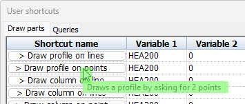
The tool has so many possible uses that it is best to explain this through the example shortcuts that are included by default :
Draw profile on lines - This shortcut will first ask you to select model lines, and then it will draw a profile on each line with the section and rotation chosen in variable 1 and 2. Afterwards, the dialog box for doing further changes to the new profile placements is opened.
Draw column on lines - This will do the same as Draw profile on lines but it will also immediately assign the structural type Column (member) to the new profiles that are created.
Assembly weight (under the Queries tab) - This will ask you to select a part, and will then display the total weight of the part's assembly in the Variable 1 field of the dialog itself.
Notice the different ways in which the properties for the new parts can be handled :
- Asked as input on the command line
- As a variable in the shortcut dialog, allowing us to set a default value there
- A fixed value stored inside the shortcut, which is un-modifiable unless the shortcut itself is being edited
To learn more about creating user shortcuts see the User shortcuts topic.
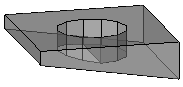
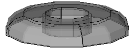
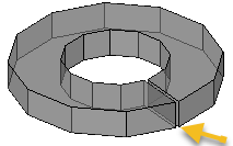
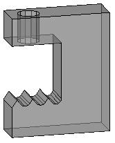
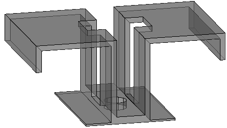
Complex bolt parts for hold down clips, domed nuts, plugs, ...
Complex bolt parts allow us to display complex geometry to represent hold down clips, bevel washers, cap nuts, nylon plugs, and any other parts that can be drawn with extrusions and/or revolutions.
There are several reasons for using complex bolt parts to draw special bolt parts instead of drawing them as regular parts or structures:
- Ease of use and automation during drafting : all commands and macros that can draw bolts allow us to draw these special parts quickly and in the right location, which is a big time saver for drafters.
- Reports generated by Parabuild will accurately list these parts as sub parts of the bolt assembly, in the same reports. If they would be drawn as separate parts then they would be listed as separate parts in the reports and drawing BOMs.
- The computer resources needed to draw these complex parts are lower so they are the requirements for the graphics card, CPU, and dwg file size are significantly reduced when these parts are used in great numbers. Parabuild uses several optimizations to optimize performance compared to normal AutoCAD/BricsCAD objects. This is particularly important when thousands of these parts are drawn in the 3D model.
How these complex bolt parts can be created is explained in the Bolt Parts database topic.
The following bolt parts were added to the standard Parabuild library of a new full installation : Bevel washer, Split lock washers, domed nuts and nylon plugs.
When you install the Parabuild version 9 update then these parts will not be installed. They will only be installed for a full new installation of version 9.
That is due to the common file names of the bolt parts, so that the update does not overwrite the changes that you did to the bolts database.
You can install the bolt parts manually with this zip file which contains all the necessary files. Care should be taken when overwriting files in your library. It may be necessary to merge the .dat files manually using a simple text editor such as Notepad.
Reviewing sheets in a separate dialog box
Reviewing sheets can now be done in a separate dialog so that two sheets in the same drawing can be compared, or the 3D model can be open at the same time as 2D sheets of the same drawing.
This is an example of the review sheet window opened outside of the main AutoCAD/Parabuild window. The GA sheet that is shown is a part of the 3D model opened in the Parabuild session.
To use this new tool, right-click on a sheet or part in the sheets manager and choose the option Review sheet in dialog :
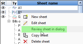
The Context menu also has options to view the sheet of a part directly in the review dialog.
The next/previous buttons in the sheets manager will open the next sheet in the review dialog box if it is already open.
One purpose of this review dialog box is to have it displayed on a secondary monitor so that you can work on the 3D model while having a sheet open at the same time. Or for editing a sheet while viewing another sheet at the same time.
Export the 3D model and paper spaces to a Dwfx file
It is now possible to export the entire project to a Dwfx file, or a single Dwfx file per part or per assembly.
The 3D model as well as the paperspace layouts are included in this export.
When writing the Dwfx file in Parabuild inside AutoCAD then part properties are written in these files (these properties are not written in BricsCAD).
The current view in model space will be the default view in the new Dwfx file.
When objects are invisible at the time of writing the Dwfx file then they will not be exported.
You can therefore hide certain portions of the model by disabling the layers in advance.
Why does Parabuild support Dwfx?
Dwfx files can be read in many free browsers on Windows, browsers and smartphones : https://www.autodesk.com/viewers/ or https://viewer.autodesk.com/ or https://bimviewer.org/
For all available viewing methods offered by Autodesk you can refer to this page : https://www.autodesk.com/viewers?fileType=DWF
The Dwfx files can contain 3D models, sheets, properties per part, and markups can be made from within the better viewers.
For example this could be a solution for :
- Making the Parabuild 3D model review-able by anyone in the cloud, no CAD required
- Reviewing the model on systems without Parabuild (third parties or shop/site)
Using the Parabuild command to create Dwf files
We can use Export BIM to file to write a single Dwfx file for the entire model, or a Dwfx file per part or assembly.
Using the publish command to create Dwfx files
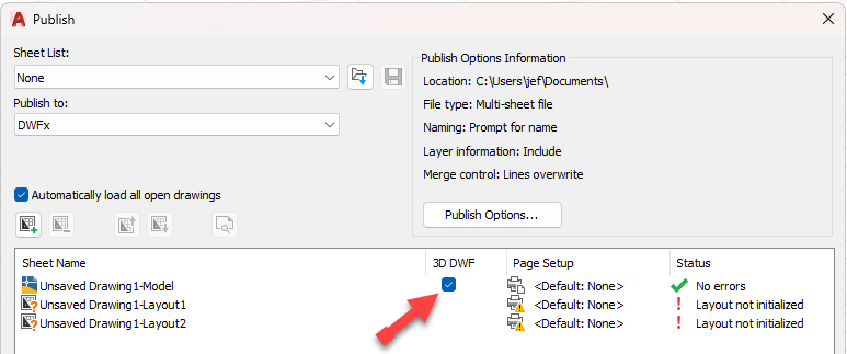
We can also use the AutoCAD or BricsCAD publish command to write a DWFx file of the entire 3D model (PUBLISH).
This file will also contain the properties attached to all Parabuild objects in AutoCAD but not in BricsCAD.
In order to write this DWFx file you have to start the Publish command and then enable the 3D DWF option for the model in AutoCAD :
How to browse the model in Autodesk Design Review
We will explain a little how to use this free viewer to see all the relevant information in the Dwfx file.
When opening a Dwfx file the viewer will look like this :
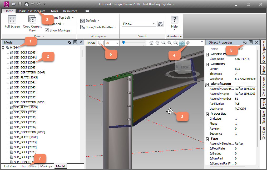
When the Model tab is open, we will see a navigation tree.
The layers of the model are the first nodes in this tree (1)
Each individual object (2) on that layer is shown as a child of the layer node
Clicking on an object in the tree will highlight the object in the 3D view, and will open the object properties of the object (5)
The object properties panel can be pinned so that it remains open all the time (5)
When clicking and dragging inside the 3D view (3) the model will be rotated.
You can switch to a better orbit tool by switching to the Turntable mode (4)
You can switch to selection mode (6) so that you can select objects in the 3D view to review the object properties that way.
At the bottom we can switch to Thumbnails and List view (7). This allows us to open all the 2D layouts that are in the Dwfx file.
We can also add markups to the file (8) but this will only work on the 2D layouts.
To learn how to change the part properties that are published in Dwfx files see the Export the to a Dwfx file topic.
Export a file per part or per assembly
Several export methods that generate a single file per part or per assembly were added.
These new export capabilities were added to the Export BIM to file command :
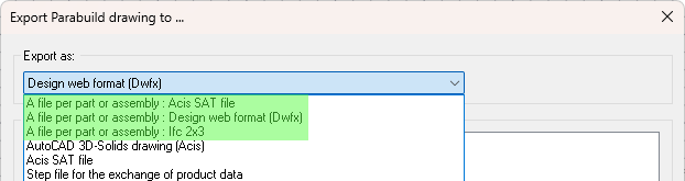
- A file per part or assembly : Acis SAT file : This was added for CNC production : some CNC machines need SAT files
- A file per part or assembly : Design web format (Dwfx) : This was added for enabling the paperless shop
- A file per part or assembly : Ifc 2x3 : This was added for some ERP solutions that support this. The ERP solution can extract some useful data from the part's Ifc file.
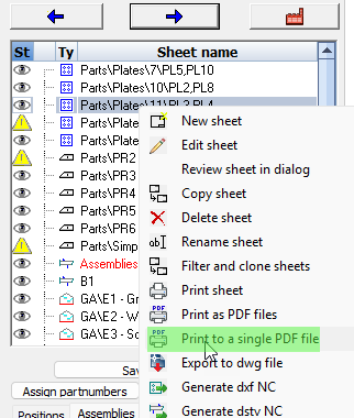
Exporting multiple sheets to a single PDF file
We can now publish a set of sheets into a single Pdf file.
This supports combining a mix of format sizes into 1 pdf file.
To use the new feature use right-click on a sheet or use the factory icon :
Filter and clone sheets allows you to make copies of a certain sub-selection of sheets such as a particular phase. The cloned sheets will contain the correct amount of parts for the filter that you chose, and sheets without parts that passed the filter will be skipped. This allows for workflows with fewer sheets to create and clean up, and only generating the filtered clones when needed.
The new tool is available by right-clicking on a sheet, or behind the factory icon click on filter and cloning on all sheets :
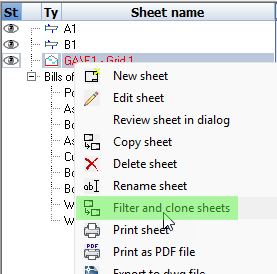
The mechanism works exactly the same as Filtering before printing, but with this tool the sheets are cloned and kept.
This allows you to review the cloned sheets before printing them.
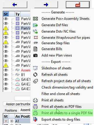
Apply sheet filters when printing or exporting sheets
When we print or export sheets we will now always see this dialog :
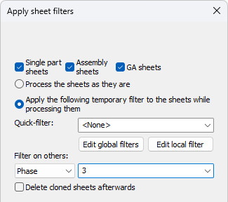
The options allow us to apply a certain filter on the sheets that will be printed or exported.
When we choose a filter here, then the sheets will be filtered like this :
- For shop drawings the amount of parts in the bill of material will be modified to be the amount of parts according to the chosen filter
- When the amount of parts on a sheet becomes 0 because of the filter, then the sheet will not be printed or exported.
- For GA sheets the chosen filter will be applied to all the views on the sheet. The parts that do not match the filter will be displayed in light grey in the views, or removed from the views.
The big advantage of this is that you do not need to create sheets for phase 1, 2, 3, ... separately.
The sheet filters are applied on newly cloned sheets. You can optionally delete the cloned sheets at the end of the print or export operation to avoid yourself the burden of having many sheets.
This way the actual filtering can be done at the last moment which can result in fewer sheets, fewer sheet checking work, and less complexity for the drafter.
This new tool will search for mistakes such as 2 sheets for the same part, missing sheets, outdated sheets, or unconnected dimensions. This will help prevent over-production, under-production, or the production of wrong parts.
This new tool can be found in the sheets manager under the factory icon :
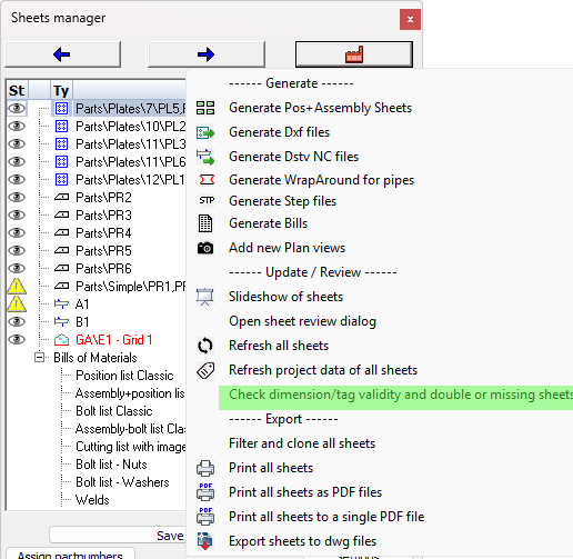
This tool will perform the following checks on all the sheets in the current drawing :
- Check whether all shop drawing views are still connected to parts/assemblies in the model, and are up-to-date
- Check whether all the dimensions and annotations are still connected to a part in the view(s)
- Check whether a particular part/assembly number is drawn on multiple sheets. Duplicate shop drawings could cause over-production.
- Check whether a particular part/assembly number is not yet drawn on any of the sheets. This could cause under-production.
We can already visually see parts or assemblies without sheets in the sheets manager.
At the end of the command a warning dialog box will appear with a listing of all the above issues that were found per sheet.
This tool will not fix any of the issues, it only provides information and changes the status of dimensions and views.
Standardize the macros using a new easy to use method
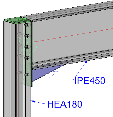
It is now possible to easily save connection values as defaults that will be loaded when the same connection is applied to the same size members in the future. The purpose is to have the configuration of the macro values stored and automatically re-used for commonly used profile sizes.
We will explain the purpose and workings of the new defaults system with an example.
Goal
This is an example macro that we get when we insert a new connection between these 2 profiles :
We want Parabuild to always use the macro with the following values, but only when the columns has an HEA180 section and the beam has an IPE450 section.
The macro has more bolts, a different bolt size, different plate dimensions, etc...
These sizes are specifically tailored to the column and beam sizes :
Work method
1) In the macro dialog that has the correctly configured values, we click on the save button :
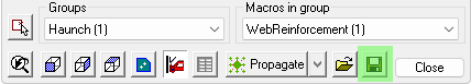
2) In the save dialog we switch to the Filtered defaults saving method, and we enter a name for this default.
The name of this file does nothing for the filtering itself. You would enter a logical name here for yourself that includes the section names so that you can update or delete the file at a later time.
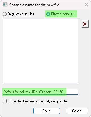
3) Save the file and that's it! In the future when the new connection is created on these members then we will see the new defaults being used :

Whereas for a connection with different member sizes, the new defaults file is not applied but instead the Parabuild built-in defaults :
How does the filtering work?
While you save the defaults file, there are 2 kinds of filters being saved :
- The macro name is the first filter. If this name does not match the new macro then the file would not be used. The name of the macro is shown here :
- The names of the base profiles are stored in the file in the order of selection. The amount of profile names thus depends on the macro as there are macros with 1, 2, 3, 4 or 5 base profiles.
In this work method you would sometimes have to save many default files so a logical naming convention that includes the base member names would be advised.
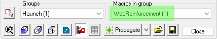
New method for macro value adoption within the same dwg file
This new feature will also help with standardization of the macros, but this time from within the same drawing only.
When active, then these commands may use the macro values of existing macros in the same drawing :
The condition for this re-using of the values of existing macros are :
- The global setting needs to be active and/or the macro setting needs to be active. See below
- The macro names need to be the same
- The macros need to have the same amount of base profiles and they need to have the same section type or size
Note There are now in total 3 different ways in which the default values of new macros can be set automatically, but only 1 of them will be used in this order :
- Saved macro defaults (new in v9)
- Defaults from the current drawing (new in v9)
- Defaults from older spreadsheets
The first default system that succeeds at successfully setting the defaults of the macro will cause a stop on defaults for that macro. The other defaults will not be applied to that macro in such case.
Note This system will only work on macros that have at least 1 base profile. Besides that the macro can also have another type of base such as a plate, a point or a line. It will not work on macros such as railing on a line or stair on a line, but for those you can still manually load saved defaults.
The global setting is located here :
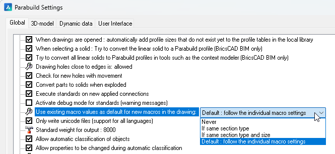
To learn more about this option see the Standardization of Connections topic.
Ifc file import improvements
Parabuild can now import non-construction geometry such as ducts and furniture as generic objects.
These can also be stored in a separate block for easier separation from the construction geometry.
The objects will be imported as mesh objects.
This allows the drafter to still see the objects that Parabuild couldn't import as steel parts for various reasons. Usually, the cause of that is that the file was generated with a software program that has no knowledge of or relation with structural steel fabrication.
Or it could be that the object is too complex for the software program to write it as an extrusion profile.
This new options can be found in the Import BIM from file dialog :
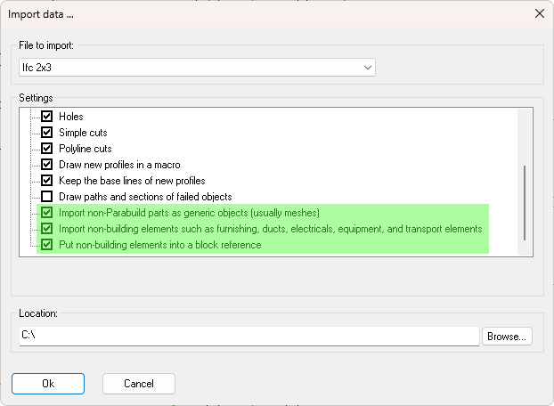
Thanks to this feature Parabuild users will only need the BricsCAD BIM Ifc import for the Bimify command to detect and convert member sizes in information-poor Ifc files. By information-poor Ifc files we mean files that are often created by non-structural steel software programs that do not write the extrusions of profiles, but instead they write these as generic boundary representations. Parabuild will still import these generic boundary representations but as meshes, not as profiles.
Other new features and changes
- New command for merging several members into a single member
- Review and remove macro option after propagating connections
- New actions inside the macro dialog box
- Adding Center of Gravity markings to views and CNC files
- Choosing the contour side of plates in DXF files in case a plate has contours on both sides
- Changes to section annotations to better support the ISO and ASME styles
- Match properties for Parabuild parts
- New command for creating members directly from a polyline to extrude. This command allows the creation of a profile with a custom section without the need to save the custom section in the library first.
- Copy/pasting views between sheets in the same drawing while keeping links to the 3D model is now supported
- Improved import of Ifc files that were generated with Advance Steel (which is now in maintenance mode) for easier migration from Advance Steel to Parabuild
- Expressions and functions are now supported inside template strings (e.g. for use in annotations)
- New macro values variables query
- New properties and changes to properties
- New macros for railings
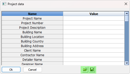
- Project data dialog addition
- The creation of 3D Solids from helical profiles is now better supported
- New options for the automatic dimensions on sheets
- More settings for the 2D views on shop and GA sheets
- New query properties were added
- New Bill of Material column types were added
- Changes to the special variables used in sheet templates
- New command for auditing part numbers in the entire drawing
- New command for auditing bolts in the entire drawing
- New capabilities for macro creation
- New Suspend macro calculation command
- New command for disabling the base bolt
Command name : PrB_MergeProfiles
It is now possible to merge several profiles into 1 single profile.
A good use case for this command is a railing handrail that was drawn with welded elbows that would need to be converted into a single bent handrail.
This command will merge the profiles together when the axii are coincident and the gaps between the profiles are not too large.
Review and remove macro option after propagating connections
When you use the propagate tool a new button will appear on top of each new macro in the model. The buttons allow you to review the new macros that were just created and allow you to delete the copies that are undesired.
It is also possible to show these delete buttons on all of the macros currently being modified in the macro dialog box.
The delete buttons will disappear when the macro dialog box is closed or when the active document is being closed or switched.
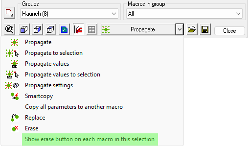
New actions inside the macro dialog box
The macro dialog box now has the following additional actions :
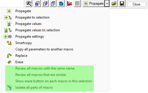
The new actions are explained below :
Review all macros with the same name - All the macros in the model that have the same name will all be modified in this dialog box
Review all macros that are similar - All the macros in the model that are similar will all be modified in this dialog box. The similarity check is the same similarity check that is used by the Propagate values tool
Show erase button on each macro in this selection - This will show a small delete button in model space on top of each macro that is currently being edited by this dialog box. This is handy for reviewing the macros that you are currently editing.
Isolate all parts of macro - This will isolate all the parts of the macro that is currently being edited.
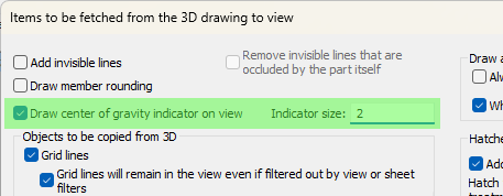
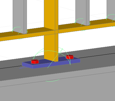
Adding Center of Gravity markings to views and CNC files
Center of Gravity (COG) marking on the view
Assembly and single part views can now show the center of gravity with a symbol :
The option for activating this can be found in the Objects to be copied from 3D to 2D views dialog box :
COG marking in Dstv CNC files
The option can be activated in the DSTV NC Settings separately per profile side :
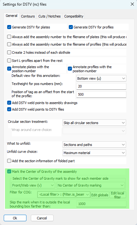
The new options are explained here :
Mark the Center of Gravity of the assembly - This option enables the Center of Gravity (COG) marking of the assembly. This marking tool only works on the main part of the assembly.
Select the Center of Gravity mark to show for each member side - This option has 2 dropdowns that work in tandem.
First choose a profile side from the first dropdown, after which the Center of Gravity (COG) type for that side is shown in the second dropdown. So we can choose a different COG type for each profile side.
The following COG types are available :
- No Center of Gravity marking - This disables the COG marking for this side, for all profiles, even if the filter explained below passes.
- Add a punch mark on COG - The COG will be indicated with a mark using the tip of the drill.
- Add a scratch '<' mark (KO block in Dstv) - The COG will be indicated with a small contour in the shape of '<'. The KO type contour is used in this case, which means scratching.
- Add a powder '<' mark (PU block in Dstv) - The COG will be indicated with a small contour in the shape of '<'. The PU type contour is used in this case, which means powdering.
The COG location in Dstv files is projected perpendicularly on the member, and centered in the web/flange. The COG will thus only be informed over the length of the profile.
Filter for COG - When no filter is entered here, then the above COG markings will be applied to all profiles.
When a filter is chosen here then the above markings per side will all be applied if the profile passes the filter.
Skip the mark when it is outside the local bounding box farther than - This option allows us to skip the COG marking when it is too far outside of the member. As the COG mark is drawn in the middle of the member web or flange, it may still be drawn when the location is outside of the member through projection. This offset allows us to choose the maximum local offset of the mark. This value is in drawing units.
Assembly COG and numbering
A new option was added to the Global settings specifically for the COG sensitivity in numbering :
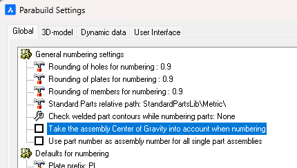
When this option is enabled, then main parts with different COG locations will receive different part numbers.
If this is disabled then 2 main parts could get the same part number even if they have different COG locations (when they are used in different assemblies). In that case, the Dstv output will still write a different file for each part but with the assembly number added to the cnc filename. Enabling this option will prevent this entire situation from occurring altogether.
Choosing the contour side of plate DXFs in case a plate has contours on both sides
We can now manually influence the contour side per plate that is written to Dxf files.
The following option was added to the DXF Settings for this situation :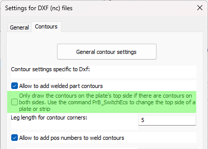
When this option is disabled then Parabuild will automatically choose the best side of the plate. When multiple parts are attached to a side then that side will be chosen. When the amount of parts is the same on both sides, then it will choose the side with the longest contours.
When this option is enabled then Parabuild will always choose the top side of the plate when both the top and bottom sides have contours.
You can use the command Switch Profile/Plate triangle direction to switch the top and bottom side of a plate or strip.
Note that for plates the long triangle is not necessarily the X axis of the plate. This triangle's orientation can be changed in the Global settings or even be replaced by a small coordinate system called Detailed Ucs icon.
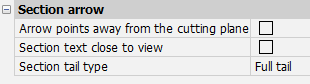
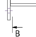
Changes to section annotations to better support the ISO and ASME styles
The following section annotation properties, which are also available in the Annotation style, will allow us to draw the section annotation in either ISO or ASME style :
|
|
|
|
ISO style |
ASME style |
Match properties for Parabuild parts
Command name : PrB_MatchProperties
This command will copy part properties of profiles, plates, bolts and structures from one part to other parts.
The command does the same as the MATCHPROP command in AutoCAD/BricsCAD, but this command copies the properties specific to Parabuild.
New command for extruding a polyline
Command name : PrB_Extrude
This command allows the creation of a profile with a custom section without the need to save the custom section in the library first.
The custom section and the new profile will both reside in the same drawing.
The command will first ask you to select the 2D polyline(s) that should be used as the section for the new profiles.
Multiple polylines can be selected for the creation of holes or for multi-sections. The result will still be 1 profile per extrusion.
The command will then ask the model lines onto which the profile should be created. At this stage you can press <Enter> to create a new line with the help of 2 points.
The model lines do not need to be close to the 2D polylines. The section will be moved and rotated to the position of the model line(s). However, placing the section polylines at the start of the path provides more control over initial rotation.
Afterwards you will still have the opportunity to position and rotate the new profile around the model line, just like any other new Parabuild profile.
Copy/pasting views between sheets
Copy/paste of views and associated dimensions and annotations to another sheet is now supported. This will no longer break the links from views to the 3D model.
Pasting views has some limitations:
- This will not work when views are pasted into a different dwg file.
- This is not intended to copy part or assembly details to GA sheets. For that use case, it is better to utilize the "Add to current sheet" feature. Pasting a GA view into a part or assembly drawing does work although that would have limited usefulness.
Improved import of Ifc files that were generated with Advance Steel
Ifc files that were created with Advance Steel will now be imported with better support :
- Profiles with an arc as path are now imported
- Assembly information is now imported
- Issues with some plates and profiles with wrong position has been resolved
- Parabuild will attempt to recreate the bolts that are stored in the Ifc file. Some guess work has to be done because Advance Steel only writes some geometry for the bolts.
This will help during the migration process from Advance Steel to Parabuild.
Expressions and functions inside template strings
We can use expressions in the template strings that are used to display text on Annotations and Bill columns.
This allows us to make the resulting text very flexible by using calculations on the variables such as + - / * and also the IF statement to make the string different based on a condition of the part.
This feature already existed in version 8 but it was beta and undocumented.
Learn how to use this new capability in the Expressions and functions topic.
New macro variable values query
In all annotations and bill fixed templates we can now use a new special query variable called MacroVariableValue that warrants more explanation.
This is an example use of this query :
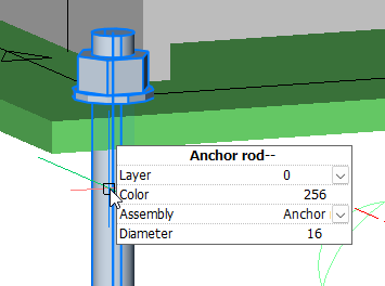
%(%MacroVariableValue.Bolts.Pattern.Count1%*%MacroVariableValue.Bolts.Pattern.Count2%)% x %MacroVariableValue.Bolts.BoltAssembly%
The above text field could result in : 4 x Anchor rod
You can learn more about the usage of this query in the Properties to be used in annotations and bills topic.
New properties and changes to existing properties
Hole side for bolts
A new bolt property was added : Hole side
This new property will be visible only when the property Maximum number of holes is in use.
We can choose the location where the first hole should be drawn : close to the start of the bolt or close to the end of the bolt.
This allows us to make the hole creation of such bolts more predictably.
Rotation for bolts
The new rotation property of the bolt will rotate the bolt around it's axis.
All of the bolt's parts will also rotate together with the main bolt.
We can use this to quickly set the correct rotation of hold down clips or other complex bolt parts in use by the bolt.
Do not drill filters for bolts
A change to the existing bolt property Do not drill filters was applied : this property now support wildcards with "*", and will also check whether the part name matches the filter.
Before this property only worked on material, remark, structural type, and phase.
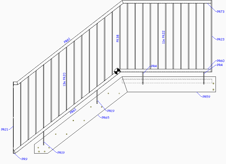
A new railing macro that draws angle profiles for rails and posts was added

A new picket rail macro that draws flat bars only was added
This macro requires some explanation because it will not draw everything automatically for you. If it would, then we would loose flexibility.
By default the posts are not drawn inside this macro. This will give us perfect distribution of the pickets.
It is therefore still your responsibility to convert a picket into a post wherever it is needed.
You can do that conversion by following this procedure :
1) Erase the macro that shortens the picket to the bottom rail
2) Break the bottom rail OR the picket, whatever you want
3) Connect the post to the beam or stringer
This is because the railing command does not connect to the beam or stringer. This is done afterwards by you, to allow maximum re-usability of the macro.
Project data addition
It is now possible to save the entire list of project data values for easy re-using in other projects :
Spiral profiles
The creation of 3D Solids from helical profiles is now better supported. This is useful for having more accurate splines on the shop drawings, and for exporting the helical profile as a step file.
New options for the automatic dimensions on sheets
The dimension settings for plates, profiles and assemblies have the following new settings :
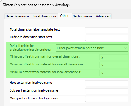
The following new verbose option makes it practical to learn and debug the dimension rules :
More options for the 2D views on sheets
- Shortening settings are now saved inside each view for new or refreshed views. This allows individual views with different shortening settings from the general settings, and will cause each view to refresh consistent with it's own saved shortening settings instead of the general shortening settings.
- It is now possible to allow or deny the shortening per view :
- It is now possible to remove the triangular shaped annotation to the left of the side views, while keeping them visible on the section view.
When doing this, one could enable an annotation underneath the sideview that contains the view number like this :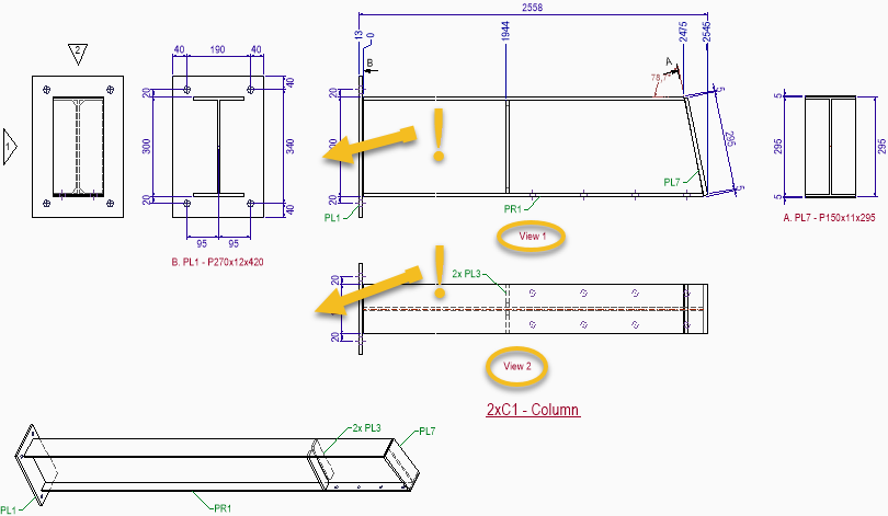
The relevant settings for disabling this triangular annotation and adding the annotation underneath the sideview like shown above can be found here :
Query properties are properties that are available in annotations, object filters, and the quick filter dialog.
They are also accessible as columns inside Bill of Materials but only through the fixed template strings which can be used in columns.
The following new query properties were added :
BoltSlotHoleAngle - This returns the angle of the bolt's slot hole in WCS coordinates
IsWeldSymbol - This returns "1" when the object is a weld symbol annotation
IsInvalidDimOrLabel - This returns "1" when the dimension or annotation is invalid. Invalid for a dimension means that the measurement failed. Invalid for an annotation means that the contents for the annotation text could not be retrieved from the annotated part.
AcadClassName - This returns the classname of the object. This will work on all objects owned by AutoCAD, Parabuild, and all other 3rd party applications. The class name for a line is LINE, for a polyline it is LWPOLYLINE, and for a parabuild plate it is S3d_Plate. To learn the class name of an object you can use the LIST command.
The following new columns were added for Bill of materials :
PbColSheetNameNoFolder - This returns the sheet name without any sub folders. This would be the same as the filename when the sheet is exported to a Pdf or dwg file.
PbColGlobalIdIfc - This returns the global id of the part as they are written in Ifc files. This global Id is calculated based on the GUID that Parabuild uses but compressed using the method explained in the Ifc standard.
Changes to the special variables used in sheet templates
Some changes have been applied to the unique variables that can be used in sheet titles. We can now display the sheet name without it's sub folder.
These are the changed and new sheet variables and some explanation of their workings :
PrB_FullFilename - This will show only the sub folder and the sheet name. The sub folder is local relative to the folder where the 3D dwg file of the project is stored
PrB_SheetName - This will show only the sheet name. This is also the filename that the sheet would get when it is exported as a PDF or 2D dwg file
PrB_3DFoldername - This will show only the folder where the dwg filename of the 3D project is stored
PrB_3DFilename - This will show the folder and filename of the dwg filename of the 3D project
New command for auditing part numbers in the entire drawing
Command names : PrB_AuditPosNumbers and PrB_AuditAssemblyNumbers
These commands will check all of the parts or assemblies in the drawing to find erroneous part numbering, possibly and fix it.
The errors that it searches for are :
- Parts/assemblies that have the same number but are not the same geometrically or by numbering-sensitive properties. A warning will be printed and one of the parts will lose its number.
- Parts/assemblies that are geometrically the same and have the same numbering-sensitive properties, yet do not have the same number. Only a warning will be printed. You might want to renumber to reduce them amount of unique numbers.
The above error described as 1) is already automatically fixed when the drawing is opened.
The Parabuild numbering system itself ensures that such numbering errors typically never occur.
These commands were created for fixing bad part numbering in older versions of Parabuild, or in cases where the user changed number settings after numbering and in doing that caused such numbering inconsistencies.
New command for auditing bolts in the entire drawing
Command name : PrB_BoltsAudit
This command will calculate the macros and will notify when some bolts required changes during the evaluation. Some of these changes could be :
* The bolt position was changed
* More or less holes for the bolt
* The bolt axis length has changed
The bolts that were changed will optionally be put on the layer "Pb-Review"
This command could be used for testing purposes in combination with the command : PrB_SuspendMacroCalculation
New capabilities for macro creation
Each constraint can now have a comment assigned to it. This comment will only be visible in the Edit macro dialog box and the purpose is to explain the reasoning and/or purpose of a constraint or set of constraints.
It is now possible to influence the direction enumeration of constraints using variables and equations.
This advanced feature is for those who create custom macros and it is explained in the Using variables to do changes to constraints topic.
This allows us to switch the direction of a plane without having to resort to an angle constraint or extra helper geometry.
Command name : PrB_SuspendMacroCalculation
Suspending macro calculation is a command that should be used carefully because it will stop all of the macros from doing any calculation.
This will effectively disable most of Parabuild's 3D modeling commands.
One valid use case that you could have for enabling this is when you have a drawing file that produces bad results when the file is opened (the results were good when the file was last saved).
When a drawing file is opened Parabuild will recalculate each macro and this may cause some differences from the last save result. This is the case when geometry of macros was deleted by mistake or during a drawing file recovery which can also delete objects to repair the file.
To fix the dwg file you would have to follow these steps :
- Suspend the macro calculation with this command
- Open the dwg file
- Delete the macros that cause problems
- Save and close the drawing
- Enable the macro calculation again
- Open the drawing again
New command for disabling the base bolt
Command name : PrB_DisableBaseBolt
This command will ask you to select a bolt after which it will disable the base bolt part.
This allows us to have the nut and washer parts only. Without this command it would only be possible to have a bolt without the base by creating a bolt assembly without base bolt. For typical uses, creating such an assembly is still the preferred method.