Version 7.0
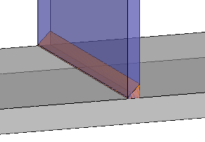
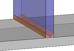
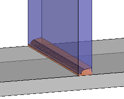
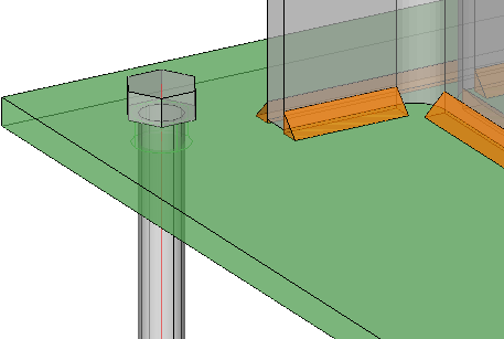
3D welds
You can now model 3D welds for the most used structural weld types. There are several advantages to explicitly modeling welds. Visualization of welds will aid the user in determining problematic welding situations and wrongly sized welds. Weld symbols will be automatically added when generating shop drawings. Bills of material of a project’s welds can help with estimating, planning and scheduling of the welders. The 3D weld objects can also receive fabrication data and get a unique number for tracking purposes. In the near future we intend to extend these capabilities to include support for robotic welding.
A traditional hurdle with modeling welds is the amount of work involved for the detailer.
To make this go a lot faster we created the AutoWeld engine that can automatically create welds based on very flexible rulesets that the user can customize. Different weld types and sizes can be automatically assigned by a ruleset based on available model information like plate thickness, angle, structural types and much more. The standard Parabuild ruleset will create most structural welds automatically and can be used as the base for your own customized fabricator specific rulesets.
Further editing of the automatically created welds is then easily and quickly done using the properties panel or the weld editing dialog, making the overall process very efficient.
These are all the topics for the creation of welds and the automatic addition of weld symbols on the shop drawings :
- A new object was created : The 3D Weld object
- It is possible to use the properties panel on the 3D Weld object. This topic also explains the purpose of each property.
- Automatically draw weld objects using AutoWeld
- Drawing welds with the context modeler
- Drawing welds from within the Macro dialog box
- Reviewing and modifying welds
- Deleting welds
- Removing weld segments
- Splitting / Merging welds
- Numbering welds
- There are settings in the shop drawings that will influence how the weld symbols are drawn and grouped on the 2D drawings.
See the Weld symbols on shop drawings topic for more information
Welding practices
If you need more general information about welding practices, we can refer you to the Structural Detailer site :
- Welding processes
- Joint types
- Fillet welds
- Weld preparations
- Basic weld symbols and an example weld for each
- ISO weld symbols
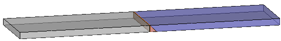
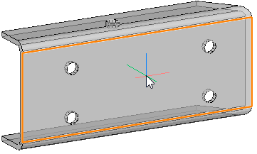
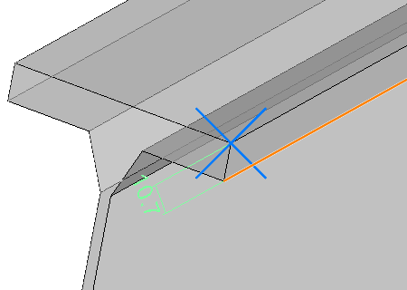
Unfolding
Parabuild can natively unfold cold formed profiles, without the need for any additional module.
Profiles will need to be modeled correctly with fillets to make the unfold work.
|
|
The following topics and new settings will help you with activating and using the unfolding tools:
- General information about unfolding and the settings for it in Parabuild
- Enabling unfolding for Dstv and shop drawings
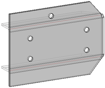
- Testing unfold in 3D
- There are rules to adhere to in order to make models unfoldable
You can read more about the unfolding rules here - There is a new option called This is a view of an unfolded part in the View settings of shop drawings
- New options are available in the Dstv options that are specifically for unfolding
- New options are available in the Dxf options that are specifically for unfolding
- The Advanced properties of the to be unfolded 3D part also has some unfold options
- The Profile section table also has some unfold options
- In the Parabuild global settings dialog box, there is an option to choose which K-factor table should be used
- A setting was added to the Sheet properties for configuring the text in the annotations of bend lines
- The properties PbBillColUnfoldedName, PbBendRadius, PbBendAnglePlusMinus and PbBendAngleUpDown were added for unfolded parts.
All of them can be used for annotations, but only PbBillColUnfoldedName can be used in bills.
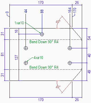
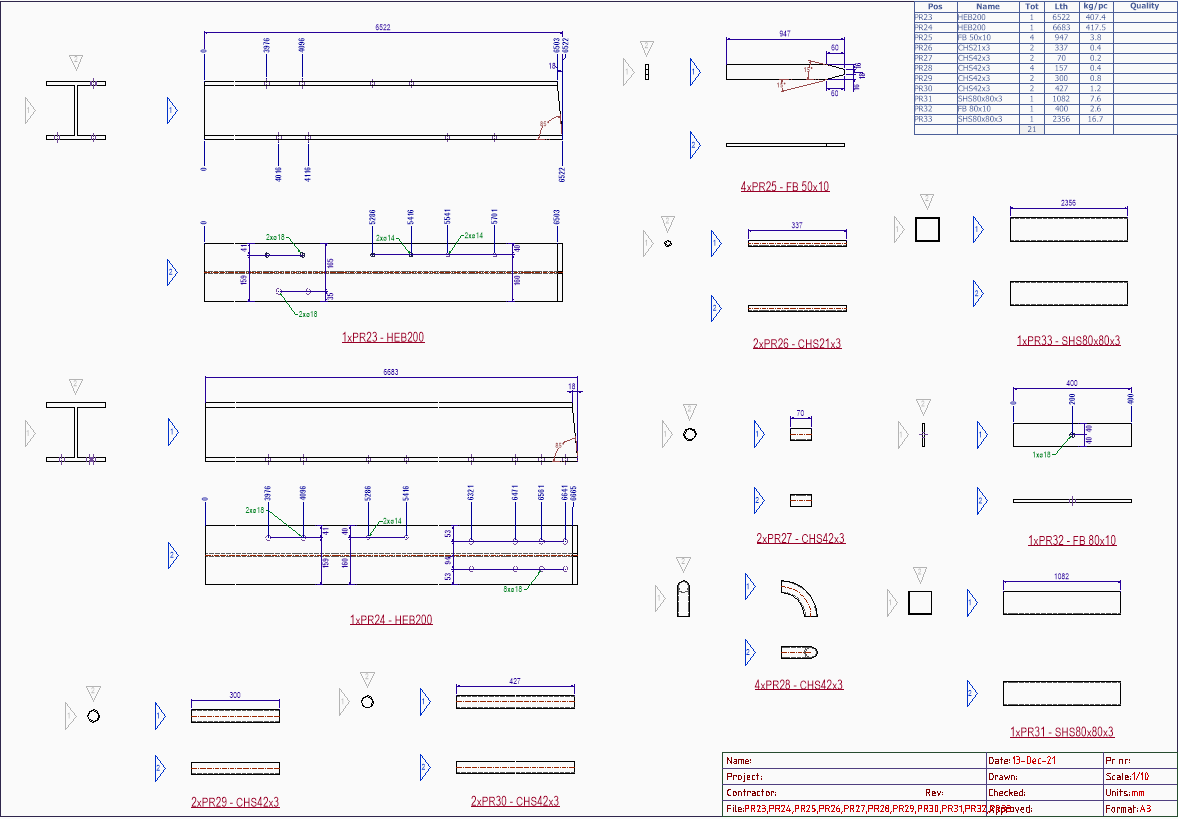
An example of an automatically generated unfolded view
For a more complete list about these new features for unfolding, you can review this section in the migration guide.
Bill of materials changes and additions
The bill of material generation tools have been replaced by a new generation system.
The new bill generation method has these improvements compared to the old bill method :
- They allow you to use many more properties as columns in the bill.
- Many new file formats for bills are now supported : Pdf, Excel xlsx, Excel xlsb, Ods, Xps, Html, Csv and Xml
- A new option Merge identical rows.
- Template files are now supported. The excel-based template file allows you to configure the layout of the bill (primarily the header and footer).
For more information about these new features, you can review this section in the migration guide.
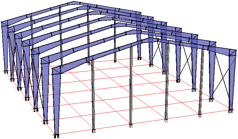
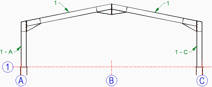
New commands and macros for PEB (Pre-Engineered Buildings)
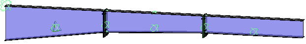
Several new commands were added to facilitate drafting of Pre-Engineered buildings.
The new commands can be categorized into 2 categories : Drawing PEB members and Drawing connections between PEB members.
You can learn all about these new connections and commands in the Pre-engineered buildings (PEB) topic.
|
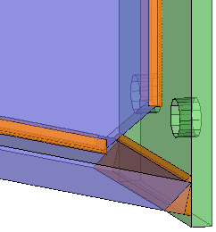
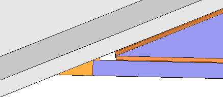
New connections group : Miscellaneous ending connections
This command collects a new set of ending connections.
These connections are similar to those found in the End / Base-Plates command, but instead of an ending plate, it draws other parts such as plate and angle cleats at the end of a profile.
The geometry that needs to be selected is 1 profile, and then 1 planar surface or nothing for footing connections.
The macros in this command were designed to be deploy-able in many different situations by requiring only 1 profile to be selected.
For the positioning of the parts, you are free to select a planar surface of any other profile, plate, structure or volume.
You can learn more about this new command in the Miscellaneous ending connections topic.
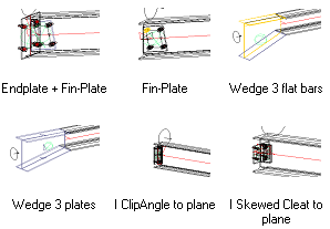
Some examples of the newly available ending connections
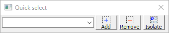
New tool : Quick select
This tool allows you to quickly adapt the current selection by removing or adding certain objects from the selection.
You can learn more about this tool in the Quick select topic.
New command : persistent measuring
With this command, you can measure the distance between 2 (sub) geometries.
The measurement will stay visible in the drawing after the command, and the value will be updated when one of the sub-geometries has changed.
You can learn more about this command in the Measure Distance topic.
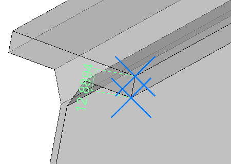
Example measurement between 2 points. |
Example measurement between a line and a point. |
New label template system for flexible property assignment in annotations
This is an example of what the label template system can be used for :
The columns would be labeled with the two closest grid lines automatically; X and Y.
The rafters would be labeled with just one closest grid line automatically; X or Y.
These are automatically drawn annotations but with properly configured label templates
You can learn more about this system in the Label templates topic.
Gather sheets
The gather sheets option will now also work on member shop drawings.
The option for enabling gather sheets can be found in the Settings for automatic generation of sheets dialog.
Additions and changes to bolts and holes
The following changes were made to bolts :
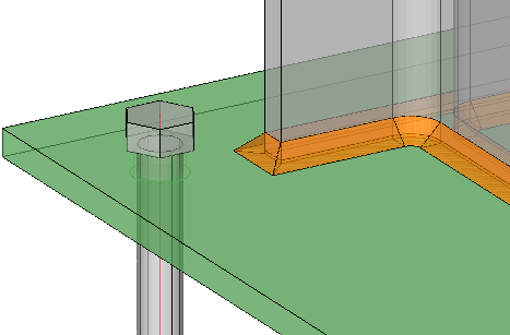
- A new advanced property was added called Only draw holes in parts that are used by the macro that draws the bolt
This option can be used to reduce the amount of holes drawn by the bolt.
For more information about this feature, see the Advanced properties of the bolt.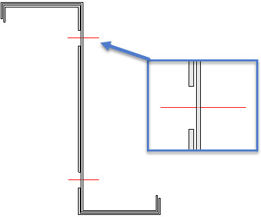
An example of helper bolts that add holes in one part, but purposefully does not add holes in the other part - A behavioral change has been applied to bolts :
When the Maximum number of holes property is used, and once the bolt is connected to the maximum amount of holes specified, then the bolt will prefer to link to the same parts, even after changes to the bolt or the parts.
To let the bolt draw holes in a different part after that, you can use the Remove hole property of the bolt to let the bolt forget it's previously linked part.
This behavioral change minimizes the risk of the bolt linking to a different part after the initial link was made.
Modifications to the Parabuild library
There is now a new folder in the library : \Parabuild\Pb_Lib\Default template files\
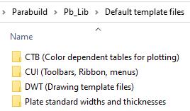
This folder has 4 sub-folders and each one has a different purpose.
This is what will happen with the files in these 4 new folders :
- The CTB files are automatically copied to the AutoCAD/BricsCAD support files folder when Parabuild is opened
- The CUI files are automatically loaded when Parabuild is opened (the actual loading will happen once a drawing is opened)
- The DWT files are automatically copied to the AutoCAD/BricsCAD templates folder when Parabuild is opened
- One of the Plate standard width and thickness files can be chosen as active file in the Library Localization dialog box
Changes to annotations on shop drawings
On each shop drawing, several annotations are automatically added underneath most views and close to parts.
The location where the contents of these annotations can be modified has changed.
You can find out all of the setting locations here : Where to change the contents of annotations on shop drawings
New options for the workshop drawings
The following new options/features were added :
- A new option in the Workshop drawing settings for the folder location where the dwg and pdf files of exported sheets should be stored.
This is a local subfolder of the main folder of the 3D drawing. - The gather sheets option will now also work on profile shop drawings.
The option for enabling gather sheets can be found in the Settings for automatic generation of sheets dialog. - 3 new clearance settings were added to the Other sheet settings dialog, so that it becomes possible to configure the minimum space that Parabuild should keep between parts, between views of the same part, and between the views and the sheet frame and sheet title.
New options for the automatic annotations and dimensions on GA drawings
The GA view tool that automatically adds annotations and dimensions to General Arrangement views has been expanded.
The dialog box has new options for annotations and dimensions on GA views such as minimum ration minimum angle and grid line dimension direction.
Other new features
- The complete Parabuild 3D drawing can now be exported to a Step file (only available with the BricsCAD Communicator license)
- It is now possible to Generate STEP Files for all members (one file per part number). Before, this function only worked on hollow profiles (only available with the BricsCAD Communicator license)
- All structure objects such as stair treads and shear studs are now exported to Ifc files
- New shortcut buttons were added to the status bar at the bottom of the screen :

They are a shortcut to the Assembly / Single Object Selection command and the Restrict Z axis for OSNAP setting in the Visibility Manager.
You can use the buttons to switch between the modes and you can also see the current mode if the button is pressed. - In BricsCAD, the properties of plates and members are now merged which makes it easier to do changes to multiple parts. This means you can now change many properties of the plates and members in a selection set in a single step. For this to work you should filter out the other types of elements in the selection set (bolts, curves, ...)
- It is now possible to automatically create a placement macro for a member that has none.
Just click on the All placement options button in the properties panel to create a new macro for the member.
To read more about this feature, see the Profile placements options in the member properties panel. - It is now possible to activate the Current UCS option in the Profile placement dialog box.
More information about this option is explained in the Profile placement tool topic. - The Profile placement tool now allows you to select any endpoint on the section, as well as any midpoint of any edge of the section.
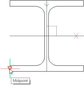
More information about this tool is explained in the Profile placement tool topic. - The history parts used by shop drawings can now be purged partially when you delete a sheet or through the existing Erase Position or Assembly history commands
- When you reset the workshop drawings settings (see below in red), then a new bill called Parts in each assembly for ERP will be added.
This new bill can be used to import into the ERP software from Construsteel. - The bill templates that are used by shop drawings can now be directly edited from within the Settings for page and layout dialog.
It is not necessary anymore to open the template file and modify the cells in the table manually : this is done automatically when you use the Modify bill button to edit the template table.
Modifying the template drawing file is now only necessary if you want to change the table text styles and other appearance changes.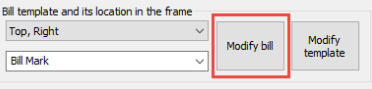
- The Profile Length Optimization command has an improved bill that more clearly shows the batch results of which parts to cut from stock lengths.
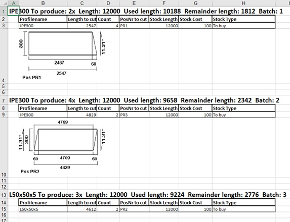
- 2 new options were added to the Bill of materials, that are specifically for the bills with cutting images :
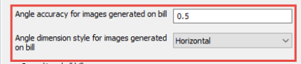
Angle accuracy for images generated on bill - Choose the accuracy to which the angles on the image should be rounded
Angle dimension style for images generated on bill - Choose the bases to which the angles should be measured.
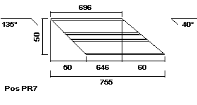
This is an example image result that was generated with the option Horizontal, always top side - When printing sheets, it is now possible to enter the number of copies that should be printed.
- It is now possible to automatically generate DXF files for all strips in the drawing.
As you know, a strip in Parabuild is actually a member. So to make this possible, the strip is converted to a 2D plate in the background.
Do note that the dxf files for strips generated this way will not get any contour or match lines. - 2 new options were added to the DSTV NC Settings that allow you to change the precision of all the values in the generated Dstv files.
- The annotations and Annotation styles have received several new properties, such as layer and Label templates.
- The following additional new fields can be used in the shop drawing title templates :
- PrB_3DFoldername - This field contains the full path to the 3D dwg filename
- PrB_3DFilename - This field contains the filename of the 3D dwg file
- The property list has been expanded.
They can be used in Object Filters, in Annotations, and in Structural types for automatically assigning the properties to objects.
- A new command was added : PrB_DefaultStockLength. It allows you to change the default length of all stock items listed in the Profile Length Optimization command.
- A new command was added : PrB_IconColorsOverride. This command allows you to set the Parabuild icons to dark or light, regardless of the current color theme of AutoCAD/BricsCAD.
- A new command was added : PrB_SetViewLimitation. This refers to the 2D front/back view limitation shown in the Visibility Manager. By allowing you to change these values through the command line, scripts, icons or tablets can now also change these values.
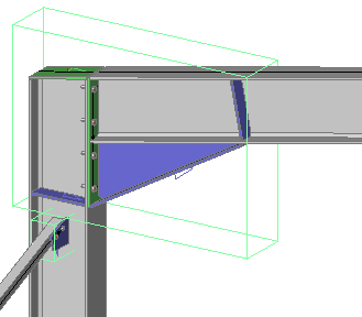
- The macro representations have 2 new properties :
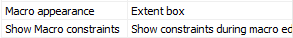
- Macro appearance : instead of a sphere, you can now enable an Extent box for the representation. The box will be drawn around the extent of all the parts that the macro owns/created :
- Show macro constraints : When you set this property to Show constraints always, then all the dimension values inside the macro are shown on screen.
The Measure Distance command uses this feature to show the distance between objects on screen. - An expansion was made for inserting macros from the library. This feature is only valuable to users that create their own custom macros.
Normally, a members-based connection that is to be inserted from the library can only have members as base (defining) objects.
But now, you can also use multiple points and Parabuild plane objects as base objects.
The Smart Copy Settings command has been modified to make this possible. This command will ask the order in which the parts need to be selected, and also the name of the points and/or planes. The name is displayed when the macro is inserted so that the user knows what point or plane to select in the correct order.
The Smart Copy command can't yet make copies of macros that use these points and planes. The new feature only works when inserting the macro from the library.